I recently had the chance to get a hands-on look at the Eidon confocal retinal scanner. The Eidon is a hybrid device combining features of a non-mydriatic fundus camera with confocal scanning technology. It is manufactured in Italy by Centervue SpA. Centervue describes this instrument as the first true color confocal scanner on the market. It is different than a confocal scanning laser ophthalmoscope in that it uses a broad spectrum white light LED (440-650 nm) rather than monochromatic lasers. A second light source provides near infrared (IR) imaging at 825-870 nm. The advantage to confocal imaging is that it suppresses out-of-focus light from reaching the image sensor. This minimizes the effect of cataracts or other media opacities, resulting in sharp, high contrast images. The confocal design also allows it to image through a smaller pupil than a typical non-mydriatic camera.
The footprint of the Eidon is fairly compact, but the instrument is taller than most fundus cameras. The device is operated via touch screen tablet and has both automatic and manual controls. The Eidon has a fixed 60 field of view, but is capable of capturing several fields and creating montage images. It features a 14 megapixel sensor to capture color, red free, and infrared images. The red free photos are extracted from the color image rather than through a separate exposure with a blue-green light source.
The capture software is incredibly simple to use. It is about as automatic as a device can get. Using the touch screen tablet, you enter the patient demographics and program it for the desired fields of one or both eyes and push the start button. The device does the rest automatically, even telling the patient to open their eyes prior to each flash capture.
The internal fixation light will step through the various fields and capture each one automatically. Auto-alignment is accomplished by identifying the center of the patient’s pupil with IR. It will then focus automatically with a range of -12D to +15D. Once focused in IR, the camera will slightly readjust focus just prior to color capture to account for the difference in wavelengths between color and IR. The autofocus works very well, but eye movement during capture can contribute a slight blur to the image.
Minimum pupil size is 2.5mm. It does capture good images at this pupil size in the posterior pole view but like any other non-myd device, it works a little better if patients are pharmacologically dilated. This is especially helpful when imaging peripheral fields or you plan to do a montage. I have found this to be true with all non-myd color fundus cameras. I would like to see separate exposure settings to reduce the gain and noise for eyes with widely (pharmacologically) dilated pupils.
Left to right: cropped images from a non-mydriatic camera, Optos composite red/green, and Eidon. Photos of the same pseudophakic eye were taken on different dates.
The resulting images appear different than what we see with either a digital fundus camera or a cSLO. Centervue refers to the broad spectrum imaging as “True Color” to distinguish Eidon images from SLO composite laser color images from Spectralis or Optos.
The Eidon attempts to address some of the limitations of digital fundus cameras that are poorly calibrated for color balance, gamma, and exposure. In doing so, it seems to sacrifice some color fidelity and a true appearance of the optic nerve. The red channel is desaturated to avoid loss of detail from oversaturation, but many Eidon images appear slightly green and might benefit from a little more red or magenta bias to the color balance.
Although the pixel count of the Eidon sensor is quite high, the color images seem a little over-processed and a bit noisy when zoomed in, probably from the increased contrast as well as the high gain settings that allow it to capture through very small pupils.
One of the features touted by the manufacturer is that it prevents “optic disc bleaching” seen with some fundus cameras. It does hold detail in optic disc photos, but the flip side to this is that the rim of the nerve can appear abnormally dark or gray, making it difficult to document pallor. Disc bleaching shouldn’t be a problem in fundus cameras that are calibrated for proper contrast and exposure.
Left: Traditional color fundus image with a well balanced 11 MP color sensor. Right: Same eye taken with Eidon.
I also played with the digital joystick and manual mode changing the level of focus to see if the instrument exhibited the confocal tonal shift seen with the Spectralis. In playing with manual mode to alter focus or exposure, it became clear that the instrument works best in full-auto mode.
We did not see the confocal tonal shift in either color or IR images when looking at elevated lesions or manually changing the focus. Left: Spectralis IR (820 nm) image of serous detachment exhibiting tonal shift from elevation. Right: Eidon IR (825-870 nm) does not demonstrate the same effect even though it is also a confocal device.
The Eidon review software is functional, but could be a little more streamlined. It would be nice to scroll though successive images, rather than having to go back and forth to the proof sheet to open each frame individually. The montage software works quite well.
The bottom line is that the Eidon is a very interesting hybrid device that combines features of confocal scanning with full color capture in a package that is incredibly simple to use. It would be a great screening tool or replacement for a fundus camera in primary eye care settings and would require minimal staff expertise or training.
Thanks to Todd Hostetter, CRA, COMT for bringing the device to the clinic for a demo, and to Jim Strong, CRA, OCT-C for help taking some of the images.
Disclaimer: I have no financial or proprietary interest in this device.
The Heidelberg Spectralis confocal scanning laser ophthalmoscope (cSLO) is a commonly used diagnostic imaging device that uses monochromatic laser illumination to image the eye. It can be used for several retinal imaging modalities including infrared reflectance (IR), fluorescein angiography, ICG angiography and fundus autofluorescence (FAF). The confocal capability of the cSLO allows it to capture high-contrast, finely detailed images.
But what does confocal actually mean and how does it work? The word confocal simply means “having the same focus”. In this case it refers to the confocal pinhole or aperture that is optically located at the same plane of focus as the subject. The cSLO utilizes a focused laser to scan the subject point-by-point and then captures the reflected light after it passes through a confocal pinhole. The pinhole suppresses out-of-focus light from reaching the image detector resulting in very sharp images. The confocal pinhole is especially effective at eliminating unwanted scatter from cataracts or corneal opacities since these structures fall far outside the plane of focus.
Left: Patient with a cataract obscuring the view of the retina and optic nerve through a fundus camera. Right: The confocal pinhole of the cSLO suppresses the scatter from the cataract improving the view of the fundus.
When imaging a patient, you can see the confocal effect as you adjust the focus to the plane of the retina where it is most light efficient. The image on screen will get brightest just as you come into sharpest focus. A secondary effect of the confocal aperture is how it effects the appearance of elevated or out of focus retinal structures.
The plane of focus effects reflectivity and appearance of retinal tissues based on depth due to the confocal aperture. All three images are at the same wavelength. Focus is on the elevated optic disc on the left image. Tonality changes as focus is shifted to the retinal surface.
Adjusting the focus knob of the Spectralis can have a dramatic effect on the tonal appearance of elevated structures such as papilledema or vitreous floaters as seen here in this video.
Note the optic nerve get progressively darker as focus is adjusted from the peak of the nerve to the surface of the surrounding retina, which starts to appear brighter. The opposite occurs in the second example. Vitreous floaters from asteroid hyalosis appear as dark shadows when focus is set on the optic nerve. As focus is shifted up into the vitreous, the floaters begin to brighten and the retina fades to dark. The brightness/exposure has not been adjusted during this tonal shift. The only change is the focus.
So what does this mean for us as diagnostic imagers? Because of the inherently shallow depth of focus of the cSLO, some ocular structures may appear dark simply because they are slightly out of focus. Elevated serous detachments or papilledema are examples of this phenomenon that I call the confocal tonal shift.
A case of central serous chorioretinopathy with a classic serous detachment that can be seen ophthalmoscopically. The cSLO image is dramatic in it’s appearance due to the confocal shift. The dark area is elevated and filled with clear fluid (not blood).
In some cases the confocal tonal shift can enhance the diagnostic information by clearly outlining the borders of an elevated area or lesion. The effect is most notable with the IR laser and in red free mode.
The confocal tonal shift in three different modalities. From left to right: IR, monochromatic blue, fundus autofluosescence. The effect seems to be most pronounced in IR mode.
The confocal tonal shift also has the potential to create tonal “artifacts” which can confound the appearance of findings like blood or hemorrhage that inherently appear dark. Vitreous opacities will appear dark because they are usually out of focus and blocked by the confocal pinhole. But are they from blood or vitreous debris? It’s impossible to tell with the cSLO since they appear the same even though one is translucent and one is more opaque when viewed ophthalmoscopically or with a fundus camera.
Vitreous debris can appear very dark in cSLO images even though it is almost completely transparent. Without a frame of reference, it is impossible to know if these dark areas represent floaters or vitreous hemorrhage.
Similarly, it is difficult to distinguish between blood and elevation within retinal tissues in conditions such as macular degeneration, retinal vein occlusions and diabetic macular edema.
Patient with bilateral diabetic macular edema (DME). There are some associated dot and blot hemorrhages present, but the dark patches are a result of elevation from the DME. Each of these dark areas correspond to elevation on OCT.Branch retinal vein occlusion (BRVO). The dramatic dark lesion is a result of both hemorrhage and elevation.
It is important to note that elevated lesions can appear dark regardless of the pathologic location in the fundus. cSLO imaging alone can’t always differentiate the anatomic location. OCT imaging or angiography may be necessary to further investigate the location of the pathology.
Left: choroidal tumor. Right: serous retinal detachment. Two very different disease processes but they appear quite similar because of the confoccal shift.
In some cases, the the confocal pinhole may suppress light that is reflected from the actual plane of focus, but is slightly blurred because of scattering from a lesion in tissue that is normally clear.
IR imaging with the cSLO can help identify paracentral acute middle maculopathy (PAMM). Although these lesions aren’t elevated, light scatter from the slight thickening in the middle retinal layers are suppressed by the confocal pinhole making the lesionappear dark. The findings are far more subtle in the color fundus photographs.
Although originally designed to image the retina, the cSLO can also be used to image the front of the eye. The confocal tonal shift may also effect the appearance of some anterior segment findings.
Patient with iris atrophy. The cSLO is focused on the surface of the iris which make these dark brown irides appear light at the plane of focus. The dark areas represent absence or thinning of the anterior iris surface. The deeper, out-of-focus, layers appear dark.
In addition to the confocal shift, light scattering from some corneal lesion types may also be suppressed by the pinhole contributing to the dark appearance of the lesion.
Corneal opacities shown with diffuse illumination and sclerotic scatter at the slit lamp. The cSLO image on the right more clearly delineates the extent of the lesion. Focus is at the level of the iris with the cornea being out of focus. Where the cornea is clear, there is no blocking effect from the confocal pinhole. But where there is scatter and reflectivity from the (out-of-focus) corneal lesion, this light is rejected by the confocal pinhole causing the dark appearance.
It is important to understand the confocal density shift when capturing or interpreting cSLO images and differentiate between structures that truly are dark from those that are simply out-of-focus. In some cases the tonal shift enhances areas of interest that may not be easily identified by other means. In others it may confound the documentation of blood or hemorrhage. A second imaging modality such as color fundus photography, OCT or angiography is often needed to present a more complete diagnostic imaging study.
Here are a few more examples:
Diabetic macular edema (DME) appears dark on the IR image from the tonal shift and corresponds to the red (increased thickness) area on the OCT false-color thickness map.Left: cystoid macular edema (CME). Right: central serous chorioretinopathy.Dark lesions on two separate patients diagnosed with one of the phakomatoses. Left: a patient with tuberous sclerosis and multiple hamartomas that appear dark from elevation. Right: a retinal hemangioma in von Hippel-Lindau disease. This blood filled lesion is dark from the blood itself rather than elevationThis case represents a rare exception to the tonal shift in an elevated lesion. Adjusting the focus up and down had little effect on the tonal density, except at the borders of the lesion. Note the very high reflectivity of the inner retina on OCT. Presumably the reflective surface of the elevated area was bright enough to attenuate the normal confocal shift.
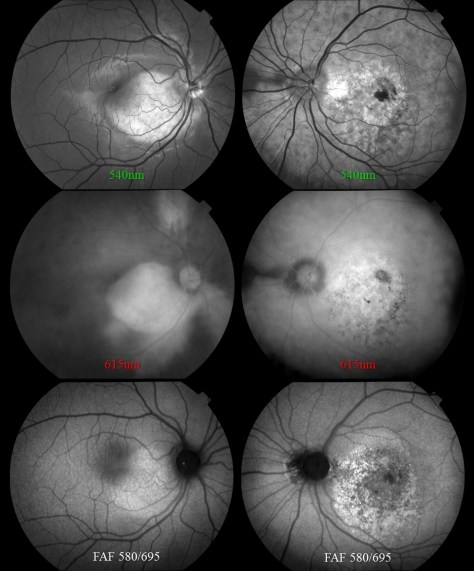
Over the past decade, fundus autofluorescence imaging has become a commonly used diagnostic technique to document the presence of fluorescent structures in the eye.1-2 The term “autofluorescence” is used to differentiate fluorescence that may occur naturally from fluorescence that is derived from application of dyes such as fluorescein or indocyanine green.
Autofluorescence is most commonly used to document fluorescence of lipofuscin, a fluorescent pigment that accumulates in the retinal pigment epithelium (RPE) as a normal byproduct of cell function.3 Lipofuscin deposition normally increases with age, but may also intensify in certain retinal abnormalities. It is used to document progression of macular degeneration, central serous chorioretinopathy, Stargardt disease, drug toxicities, and several hereditary retinal dystrophies.
In addition to the documentation of lipofuscin in the RPE, there are other fluorescent findings that may occur in the eye. One of the initial uses of autofluorescence was documenting optic disc drusen and astrocytic hamartomas as early as the 1970’s.4 Both of these entities are calcified lesions that are highly fluorescent and can be documented with standard fluorescein excitation and barrier filters.
Left: optic disc drusen. Right: astrocytic hamartoma, a calcific tomor associated with tuberous sclerosis
The aging crystalline lens is also known to be fluorescent. In fact, lens autofluorescence was the inspiration for the development of fluorescein angiography by Novotny and Alvis.
Dense cataract that fluoresces with the standard fluorescein excitation and barrier filter combination in a fundus camera. This image illustrates how fluoresence from the lens can compromise the qulaity of a fluorescein angiogram by adding unwanted fluorescence.
In addition to these well-known entities, there are some additional autofluorescent findings you may encounter in the eye. In 2009, Utine et al reported autofluorescence of pingueculae on the ocular surface.5 This finding may interfere with photo-documentation of topical fluorescein staining patterns in patients with conjunctival lesions.
Autofluorescence image of a pinguela taken with a fundus camera in external mode. Note that the crystalline lens of this eye also fluoresces.
Certain emboli, presumably calcific, exhibit fluorescence.
Patient with a branch retinal artery occlusion. Left image demonstrates classic retinal whitening from the occlusion. Right image identifies the fluorescent calcific plaque associated with the arterial blockage.
We’ve also had a case of corneal blood staining that fluoresced. As it turns out, hemoglobin and hemosiderin are known to be fluorescent and that’s what fluoresced in this case.
A case of corneal blood staining after a long standing hyphema. Autofluorescence is presumably from either hemoglobin or hemosiderin.Another case where blood is hyperfluorescent in a patient with angioid streaks.
There may be other ocular findings that exhibit autofluorescence when excited with light of specific wavelengths. Have you noticed anything else that fluoresces? If so, I encourage you to share them.
von Ruckman A, Fitzke FW, Bird AC. Distribution of fundus autofluorescence with a scanning laser ophthalmoscope. Br J Ophthalmol 1995;79:407-412.
Spaide RF. Fundus autofluorescence and age-related macular degeneration.
Ophthalmology 2003;110:392-9.
Delori FC, CK Dorey CK, G Staurenghi G, et al. In vivo fluorescence of the ocular fundus exhibits retinal pigment epithelium lipofuscin characteristics. Invest Ophthalmol Vis Sci 1995;36:718-729.
Kelly JS. Autofluorescence of drusen of the optic nerve head. ArchOphthalmol 1974;92: 263-264.
Utine CA, Tatlipinar S, Altunsoy M, et al. Autofluorescence imaging of pingueculae. Br J Ophthalmol 2009;93:396–399.
On a recent trip through Virginia, I stumbled across a gem of a museum tucked away in historic downtown Staunton, VA. I had been browsing brochures of local attractions on a stand in the lobby of my hotel and spotted a photo of a vintage view camera. The brochure was for the Camera Heritage Museum. The non-profit museum bills itself as the largest camera museum on the East Coast. It wasn’t far from my hotel, so I decided to visit, not knowing what to expect.
I walked into what obviously had once been a camera store jam-packed with cameras of all shapes, sizes and vintages. There was a gentleman sitting behind a counter in the back, busy doing some maintenance on a camera. He looked up briefly, said hello, and went back to his work while I browsed through the impressive collection. I saw everything from miniature spy cameras to large format portrait view cameras.
I recognized some cameras that I had used in my early days in photography including a Crown Graphic 4×5 press camera, a Graphic View (first monorail view camera design), several early polaroid cameras, a 16 mm Minox and many others.
After a few minutes of browsing, I asked the man behind the counter a few questions about some cameras that I recognized. When I showed genuine interest in the cameras on display, he stepped out and started describing the history, significance and stories related to many of the items on display. His name was David Schwartz, and he is the curator of the museum. He’s a wealth of information. As more people entered the museum, he recounted some of the same stories several times over, each time with the enthusiasm of someone that clearly loved cameras and the history of photography.
The collection includes vintage view cameras, military cameras, spy cameras, aerial cameras, stereo cameras, underwater cameras, Kodak Brownies, Hasselblads, Leicas, Voigtlanders, Nikons, and some truly unique cameras including a 40″ long baseball camera with lever activated focus stops preset for the distance to each of the bases on the diamond.
Folmer Graflex Baseball Camera
David and I talked about some of the stereo cameras on display and I told him that as a medical photographer I regularly take stereo photos of human retinas. He nodded and directed me to a case which held a collection of Topcon 35mm cameras including a body from a vintage Topcon fundus camera.
A Topcon 35mm camera back from a fundus camera is tucked in the back of this glass case.
When I explained a little bit more about fundus photography, he listened intently and I can imagine that he’ll include some of what I told him about this equipment in explanations to future museum visitors.
The venue for this museum is a little quirky, but it houses a serious collection of over 2000 cameras, photos and accessories. A unique feature is the fact that it is an open and accessible to the public, rather than a private collection. The museum also has an online presence. Their website contains a wealth of information on the history of photographic equipment, especially the online gallery of some of the many cameras in their collection. It’s a great resource for history buffs and vintage camera enthusiasts.
The museum can be found at the old Camera and Palette store at 1 West Beverley Street in Staunton, VA. If you are travelling through the area, it is definitely worth a visit. Better yet, if you have some old film cameras collecting dust in a closet you might want to consider contributing to the collection by donating them to the museum. They are always looking for cameras, photos and accessories with historic significance.
Did you ever wonder how ophthalmic diagnostic findings get their names? If you feel like there is no rhyme or reason to the naming conventions used in ophthalmology, you are not alone. Ophthalmology (and medicine in general) does not have structured system of nomenclature like some other sciences.
For example, the field of chemistry utilizes the periodic table of elements to organize and classify fundamental information. Biology employs Linnaean Taxonomy, which is an organized hierarchical system of classification including kingdom, phylum, class, order, family, and genus, to differentiate and name species. It was established and organized by Carl Linnaeus in the mid 1700’s and results in a naming convention known as binomial nomenclature.
In binomial nomenclature, this common Tiger Swallowtail butterfly is known as Papilio Glaucus. It was classified and named by Linnaeus himself in 1758. Papilio is latin for butterfly and glaucus means blue.
Human anatomy and medicine is a different story however. Historically there has been controversy, disagreement, language differences, and confusion amongst anatomists regarding universal terminology. To address this, there have been attempts to standardize terminology in human anatomy. Nomina Anatomica was the international standard on human anatomic terminology from 1956 until it was replaced by Terminologia Anatomica in 1998. But in ophthalmology, as in much of medicine, there is no universal system of classification for ocular anatomy, clinical findings, or diseases. It’s a bit of a “free-for-all”. In the late nineteenth century some 50,000 terms for various body parts were in use. The same structures were described by different names, depending on the anatomist’s background: school, language, culture, traditions, etc.
Let’s take a look at some of the ways that diseases are named in ophthalmology. Clinical findings may be named for their anatomic location, clinical appearance, etiology, disease process, or end result. They may also be based on etymologic roots or finally, eponyms.
A common and logical diagnostic naming convention is simply descriptive of a disease process like vitreomacular traction or corneal erosion.
Or it could be the anatomic result of those processes such as a macular hole that results from vitreomacular traction or a corneal ulcer that arises from erosion.
Some terms are based on clinical appearance, either the literal appearance or a resemblance to something else. Pink eye or floppy lid syndrome are conditions that are literally descriptive of their appearance.
Conditions like bear tracks, bullseye maculopathy, cotton wool spots, morning glory nerve, birdshot choroidopathy, and several others often bear a resemblance to something that would be commonly recognized or understood.
Other names may be based on etymology, which means they originate from traditional Greek or Latin root words.Heterochromiais a good example as it comes from the Greek roots heteros which means different, and chroma which means color.
Cataractis an interesting term that may be related to the opaque lens’ resemblance to rushing water of a waterfall, or possibly to one of the earlier etymologic roots meaning a covering or impediment.
Some conditions are probably better known by the acronym representing the full name: ARN, CHRPE, APMPPE, etc.
Finally, many conditions are based on eponyms meaning they are named for a person, usually the person that first identified or described the condition in the literature. Eponyms are a longstanding tradition in science and medicine, and being awarded an eponym is considered an honor.
Anatomists seem to have been especially fond of naming structures for themselves as seen by the many eponymous anatomic terms in ophthalmology: Bowman’s Membrane, Descemet’s Membrane, Canal of Schlemm, Annulus of Zinn, Schwalbe’s Line, Tenon’s capsule, and Bruch’s Membrane to name just a few.
Purtscher’s retinopathy is an example of a well-known eponym in ophthalmology. In 1910, Austrian ophthalmologist, Otmar Purtscher (1852-1927) described a retinopathy of bilateral peripapillary patches of retinal whitening and hemorrhages after compression injury to the head.
Eponyms extend beyond anatomy into diagnoses as well. Conditions have been named for Sjögren, Krukenberg, Stargardt, Marfan, Elschnig, Thygeson, Vogt, Cogan and countless others. We certainly shouldn’t overlook Austrian ophthalmologist Ernst Fuchs, who described several conditions and has his eponym associated with many of them. Eponyms may also be proper names of places ( Lyme Disease, North Carolina Macular Dystrophy) or famous patients: Lou Gehrig’s Disease (amyotrophic lateral sclerosis) or Tommy John surgery (named for Major League pitcher, first person to undergo the procedure).
With all these names and egos involved, there has often been confusion and controversy over who was the first to fully describe a condition. Bergmeister’s papilla and Mittendorf dot are eponyms given to remnants of opposite ends of the embryonic hyaloid artery. Vogt-Koyangi-Harada disease is named for three investigators who independently described different manifestations of the same underlying condition. Stevens-Johnson syndrome, named for pediatricians Albert Mason Stevens and Frank Chambliss Johnson, also has several other eponyms associated with it including names such as: Baader, Fiessinger, Rendu, Fuchs, Klauder, Neumann and Hebra – whew! Further confusing things are hyphenated or double surnames such as Robert Foster-Kennedy (Foster-Kennedy syndrome ) and Roger Wyburn-Mason (Wyburn-Mason syndrome).
Dilated and tortuous retinal vascular abnormalities are a hallmark of Wyburn-Mason syndrome. Findings also include arteriovenous malformations in the midbrain in this rare condition named for British physician Roger Wyburn-Mason who described it in 1943. It is also known as Bonnet-Dechaume-Blanc syndrome, named for the group that described it in 1937.
In fact, Wyburn-Mason syndrome had been previously described in the French literature and is also known as Bonnet-Dechaume-Blanc syndrome. So the correct eponym may depend on what language you speak.
Eponyms are often controversial, especially when questions arise about the moral and ethical character of eponymous honorees. There has been sparring in the literature for years over the use of eponyms and the worthiness of some of the individuals that have conditions named for them. Pulido and Matteson ask the question, “Is it worth having eponyms at all?” in an editorial in Retina in 2010. They go on to state, “Although they can function as a memory aid, they do not enhance understanding of disease…. It is best henceforth to not name new diseases with eponyms and to start moving away from their use completely.”
Stargardt disease was described by Karl Bruno Stargardt in 1909. In 1997, researchers identified a mutation in the ABCA4 gene as the cause for this hereditary retinal disorder. Many hereditary diseases are now being referred to by their identified gene mutation rather than an eponym.
Wikipedia lists some of the pros and cons of eponyms in eponomously named diseases and briefly talks about current trends:
“The current trend is away from the use of eponymous disease names, towards a medical name that describes either the cause or primary signs.”
“The scientific and medical communities regard it as bad form to attempt to eponymise oneself.”
Then there is Stigler’s Law of Eponymy, which states, “No scientific discovery is named for the original discoverer.” As proof, Stigler freely admits that others postulated the idea before he named it for himself! In describing Stigler’s Law, Malcolm Gladwell stated, “We think we’re pinning medals on heroes. In fact, we’re pinning tails on donkeys.”
David Cogan talked about the pitfalls and limited life of eponymous designations in an editorial in the Archives of Ophthalmology in 1978. Yet Cogan-Reese syndrome was named for him and Algernon Reese many years ago.
When a new designation, ICE syndrome, was suggested as a unifying term to replace Cogan-Reese syndrome, Chandler syndrome, and essential iris atrophy, Cogan was quoted by William Spencer in another editorial in Archives: “Better a descriptive name, if that is possible, and an eponym if it is not possible. Now the syndrome described by Al Reese and me is characterized by nodules, unilateral glaucoma, Descemet’s membrane and endothelial extension; why not call it by the acronym NUDE syndrome? This would give it sex appeal and put the Archives right up there with Esquire.” Cogan’s response suggests he thought eponyms still have their place – especially when it came to one named for himself!
Surprisingly, these trends and opinions haven’t prevented the coining of new eponyms in ophthalmology. In 2013, a new anatomic layer of the human cornea was first described by Harminder Dua in the journal Ophthalmology. There was even a big splash in the mainstream scientific news and social media about this exciting new discovery and the investigator who identified it. As you may have already guessed, the finding is called Dua’s layer. He named it for himself!
Despite all the controversies, confusion, and egos involved, it seems as if eponyms in ophthalmology are here to stay, at least for now. So try not to be confused or frustrated when comparing Fuchs’ corneal dystrophy with Fuchs’ heterochromic iridocyclitis, or if you have difficulty remembering whether it is Best’s or Behcet’s disease that has macular vitelliform lesions. We might as well embrace these long-established eponyms – warts and all.
Resources Here are some great resources to look up information on eponyms in medicine and ophthalmology:
Whitmore I. Terminologia anatomica: new terminology for the new anatomist. Anat Rec. 1999 Apr 15;257(2):50-3.
Lamy R, Dantas AM. [Anatomical nomenclature in ophthalmology]. Arq Bras Oftalmol. 2008 May-Jun;71(3):446-58. Portuguese.
Pulido JS, Matteson EL. Eponyms: what’s in a name? Retina. 2010 Nov-Dec;30(10):1559-60.
Grzybowski A, Rohrbach JM. “Eponyms: what’s in a name”. Retina. 2011 Jul-Aug;31(7):1439-42; author reply 1442-3.
Grzybowski A, Rohrbach JM. [Should we abandon the eponym ‘Wegener’s granulomatosis’? A historical excursion]. Klin Monbl Augenheilkd. 2011 Jul;228(7):641-3.
Cogan DG. The rise and fall of eponyms. Arch Ophthalmol. 1978 Dec;96(12):2202-3.
Eagle RC Jr, Font RL, Yanoff M, Fine BS. Proliferative endotheliopathy with iris abnormalities. The iridocorneal endothelial syndrome. Arch Ophthalmol. 1979 Nov;97(11):2104-11.
Spencer WH. Proliferating terminology and the NUDE syndrome. Arch Ophthalmol. 1979 Nov;97(11):2103.
I’ve long been fascinated by this Calotype taken by William Henry Fox Talbot and Nicolaas Henneman. It appears in several biographies of Talbot as well as historical accounts of the early days of photography. Talbot was one of the early pioneers of photography and some historians argue that it was he, and not Louis Jacques Mandé Daguerre, who should be credited as the true inventor of photography. Although that controversy may never be resolved, it is clear that Talbot was devastated by Daguerre’s recognition and celebrity. Talbot spent the next several years trying to balance the scales in his favor.
Soon after patenting the Calotype in 1841, Talbot invested in the Reading Establishment, a photographic studio and printing business started by his former valet Nicolaas Henneman in the town of Reading outside of London. The business operated from 1843-1846 and it was here that the photographic prints for Talbot’s Pencil of Nature were produced. This book, the first to be illustrated with photographic prints, represents an important milestone in the history of photography.
According to several descriptions of this well-known photograph, the scene depicts Talbot at work in the Reading Establishment. I’ve often wondered if this image wasn’t some sort of elaborate multiple exposure self-portrait that Fox Talbot and his assistant concocted. The individuals in the photo look quite similar in appearance. Could they be the same person? One could argue that Fox Talbot is both the photographer and subject, while the person standing both to the far left and inside the building look remarkably similar in appearance as well.
Is it possible they could have sequentially masked different parts of the scene during exposure to create a composite? Or perhaps they combined multiple paper negatives to achieve a final print. Talbot’s Calotype process resulted in paper negatives that were then contacted printed, while the Daguerrotype was a direct positive process that could not be reproduced. Talbot’s paper negative process would easily lend itself to composite printing.
Since no one from this photo is alive to dispute my theory, I choose to believe they somehow masked part of the scene and moved around during the exposure to place Talbot in multiple positions. I can imagine Talbot, still stinging from Daguerre’s fame and fortune, running from spot to spot to get into position between separate exposures muttering to himself, “Take that Daguerre, you can’t do this with your Daguerrotype…”
If, in fact, this image does depict multiple Talbots, it’s just as likely to have been compiled during printing. Combination printing evolved along with photography and goes back at least as far as the 1850’s. Oscar Rejlander and his friend Henry Peach Robinson both created well-known, but controversial, composite images using elaborate combination printing techniques. Rejlander in fact learned the craft of photography and printing from Henneman. Is it possible that Henneman and Talbot were already experimenting with combination printing when the image of the Reading Establishment was created?
In doing a little more research, I discovered that this is indeed a composite image, but not exactly what I expected. Often displayed as a single image, it is in fact one half of the composite photograph shown here. According to captions, the left hand image depicts Talbot as photographer, while the right hand image shows Henneman at work.
Long before the days of digital imaging and photo editing software a number of photographers used multiple exposures and combination printing techniques to painstakingly create composite photographs or photomontages. Reijlander and Robinson were followed by Jerry Uelsmann and others.
With the digital photo editing tools available today, it is relatively simple to combine elements of different images in composite form. In ophthalmic imaging we use auto-montage tools to create composite images from two or more fundus photos. Although it opens endless creative possibilities, digital imaging takes some the fun and challenge out of traditional multi-exposure and combination printing techniques.
I recently created a composite selfie (of sorts) as an homage to the early pioneers of composite photography. Taken in the Felsenkeller brewery museum in Monschau, Germany, it depicts a room filled with a vast collection of beer bottles from around the world. To me, it’s reminiscent of Talbot’s photograph of the Reading Establishment.
Although the same individual appears three times in the image, it is not combined from multiple exposures or manipulated with Photoshop. The image is unaltered from the original camera file with the exception of resizing it for the web. It was created entirely in-camera, using the panoramic feature of an iPhone. During capture, panning was paused long enough for me to move into the next position before panning resumed. As I was moving from position to position, I thought again of the Talbot image and whether he had moved from spot to spot to pose as both photographer and subject. It would be pretty cool if he did.
Photography has come a long way since Talbot invented his process in 1839. I wonder what he would do with today’s photographic tools and processes.
One of the cool things about being an ophthalmic imager is the teamwork that can develop with the ophthalmologists you work for. They rely heavily on the images you provide to help diagnose various eye conditions. I’ve been fortunate to work with physicians that rely not only on my imaging expertise, but also my experience in recognizing clinical features of unusual conditions. Recently, one of our medical retina specialists (my boss) challenged my diagnostic skills with an unusual case.
The photo request came through as a post-it note that simply listed the patient’s name and the words: “Fundus photos & OCT”. There was no diagnosis listed or specific instructions given. I called the patient in to the imaging suite and it was a teenage girl accompanied by her mother. I asked if the doctor had given them any paperwork for me and the patient’s mother said, “No. Doctor Q said he wanted to see if you could guess the diagnosis”. Dr. Q and I have worked closely together for twenty years and I can often anticipate exactly what type of images he needs without much direction. But this was unusual. The lack of information was clearly deliberate on his part, which got me thinking:
Is he testing me?
Or does he need my help in making the dx? Yeah that’s it.
Wait… He’s Chairman of the Department, a sub-specialist in medical retina, has written a textbook/atlas of retinal diseases….
He’s clearly testing me, but it must be a rare condition. Hmmm….
Aha! He probably wants images for his new book.
These thoughts are swirling through my mind as I start with an OCT of the right eye. The IR fundus image shows a large oval area that is dark from elevation. It’s suggestive of a serous retinal detachment, but the OCT shows no fluid. The retinal pigment epithelium is pushed forward suggesting a choroidal lesion.
I start going through a differential diagnosis process in my mind as I continue to capture images:
Nope, not a serous detachment. There’s increased choroidal reflectivity and thickening which suggests a choroidal tumor or nevus of some type.Could it be a melanoma or an osteoma?
Osteomas are pretty rare. I’ve seen one case in the past 30 years. Probably not…
I move to the fellow eye and the OCT shows significant pigmentary changes, subretinal fluid, and what looks like a choroidal neovascular membrane.
Hmmm…. The findings are more dramatic in the left eye. Looks like maybe an exudative process in a young patient … could it be Coat’s Disease?
I move the patient to the fundus camera and peer through the eyepiece.
Yikes! I wasn’t expecting that. Maybe I was right to think Coat’s.
Coat’s disease is an idiopathic developmental retinal vascular abnormality in children.
Characteristic findings include telangiectatic vessels with aneurysmal dilation and exudative detachments.
But Coat’s doesn’t quite fit in the right eye. Maybe Vogt Koyanagi Harada disease (VKH)?
Features of VKH include: choroidal thickening, hyperemic optic disc, multi-lobed serous detachments and de-pigmentation and clumping of the RPE late in disease.
Although some of the features fit, the characteristic serous detachments of VKH aren’t present. Both Coat’s and VKH are unusual, but not rare. At least not rare enough for Dr. Q to challenge me like this.
I shifted the camera to the left eye to take photos. Once again I was surprised at the clinical appearance.
At that point I must have smiled a little because the patient’s mom asked if I knew the condition. I said yes. Although it looked somewhat like Coat’s, I was almost certain it was a case of bilateral choriodal osteomas. A moment later, Dr. Q came into the imaging suite and confirmed the diagnosis as choroidal osteoma. Sure enough, he wanted good photos for his next book!
Choriodal osteomas are benign ossifying tumors of the choroid composed of mature bone elements. They often demonstrate a thin plaque-like yellow-tan lesion in the macula with sharp, scalloped borders. They are usually unilateral, but can be bilateral. Symptoms include metamorphopsia, scotoma and blurred vision. Vision loss may be due to direct tumor involvement or secondary to choroidal neovascularization with subretinal fluid, lipid, or hemorrhage.
Now that the mystery was over and I had passed the test, Dr Q. handed me the patient’s chart as I finished up the photo session. Her clinical findings were listed:
B-scan ultrasonography demonstrated classic highly reflective plaque-like structures with an acoustically empty region behind the tumors.
This case prompted me to look up the previous case I had encountered nearly twenty years ago. It was before the advent of OCT, but the osteoma was well documented with multi-spectral monochromatic imaging, color fundus photography, fluorescein angiography and B-scan ultrasonography. Dr. Q included that case in his retinal atlas and I had used it lectures on multi-modality imaging. The clinical appearance was quite striking and unforgettable.
It’s great when physicians challenge their staff to take an active role in a team approach to eye care. I’m fortunate to work with physicians like Dr. Q, who challenge me to not only capture high quality images, but to recognize the clinical features of routine and rare cases. Luckily, I passed this test!
Ophthalmic photography has long played an important role in the documentation and diagnosis of ocular diseases. Ocular photography is used to record medical conditions, track disease progression, and create illustrations for publication and education. The primary role of ophthalmic imaging however goes well beyond documentation in its ability to aid in diagnosis of a broad range of eye conditions. Treatment plans derived from the diagnostic information provided by ophthalmic images have benefited countless patients, as ophthalmologists use images for decision making purposes on a daily basis, and in some cases, rely on photographs as a “road map” to guide therapy.
The history of ocular photography dates back to the late 1800’s when Jackman and Webster described a technique for photographing the retina of a living human subject. The next fifty years witnessed a slow advancement in instrumentation and techniques. Photographic results were mostly inadequate due to slow film speeds, long exposures, and inconsistent light sources. In the 1950s electronic flash and 35mm cameras were adapted to ophthalmic instruments and modern ophthalmic photography was born.
There is a compelling connection between this photographic discipline and our subject, the human eye; a connection that goes beyond the obvious parallels between eye and camera, cornea and lens, iris and aperture, retina and film. We use the visual art of photography to identify problems in another visual system – the eye itself. Optical instruments used to examine or photograph the eye often utilize the optics of the subject eye to help in visualizing the target pathology.
Ophthalmic photography can at times be simple or incredibly complex. Ocular tissues can be opaque, translucent, or transparent and may require different strategies to record these structures photographically. Enhancement of anatomic features is sometimes necessary, and can be achieved by using fluorescent dyes, monochromatic light, or specialized optical devices and techniques to adequately document subtle pathology that would otherwise not be visible.
Creativity and aesthetics have their place in this field and many ophthalmic images transcend their scientific purpose and achieve artistic merit, but it can be heartbreaking when the most photogenic or aesthetically pleasing subjects present themselves because a patient’s vision is severely compromised. Enthusiasm for creative imaging can suffer in the context of tragic loss of vision. This is balanced however, against those times when an imager captures great images that help preserve a patient’s vision. Unfortunately not all images will be of sufficient quality to warrant public display or publication. The challenge for ophthalmic photographers is to provide consistent clinical images of adequate diagnostic quality, even under adverse conditions.
By providing support for education, research, and clinical eye care activities, ophthalmic photographers have been an integral part of the professional eye care community for decades. As new diagnostic imaging and treatment modalities are developed, the role of the ophthalmic imager will evolve and continue to play an important role in the preservation of sight.
I first heard this expression many years ago when a retina specialist was explaining the results of a fluorescein angiogram to a patient and her family. He went on to explain that her retina represented the “film” in the camera and that it was swollen with fluid and wrinkled, which was the cause of her blurred vision. Everyone present easily understood the analogy, as 35mm cameras were commonplace at the time. The idea of warped or wrinkled film resonated as an analogy.
Although it was my first time hearing this comparison, it was not a new or unique concept. The compelling connection between the eye and camera dates as far back as the 16th century when Leonardo DaVinci drew a comparison between the camera obscura and the human eye. In the next century, Della Porta, Cigoli, and Descartes also made a similar connection in their writings on optics and vision.
With the introduction of practical photographic methods in 1839, the analogy soon extended beyond the optical comparison between eye and camera obscura to include the comparison between vision and imaging. As photography and cameras quickly grew in popularity, scientists, physicians and ophthalmologists such as Helmholtz and LeConte advanced the analogy between photographic camera and the eye.
“The further explanation of the wonderful mechanism of the eye is best brought out by a comparison with some optical instrument. We select for this purpose the photographic camera. The eye and the camera: the one a masterpiece of Nature’s, the other of man’s work.”
Joseph LeConte
From the earliest days of photography, several investigators sought to use the camera to document the condition of the eye. Due to the technical limitations of available photosensitive materials and the difficulty in illuminating the interior of the eye, fundus photography became the “holy grail” of medical imaging. Over the next several decades there were incremental advances in optical instrumentation and photographic processes, all moving steadily towards practical examination and photography of the eye. The most notable of these milestones was the 1851 introduction of the ophthalmoscope by Helmholtz.
Lucien Howe, one of the early pioneers in fundus photography echoed the idea of eye as camera in his 1887 article in which he described having captured the first recognizable fundus photograph:
“We know that the eye itself is a camera, and when placed behind an ophthalmoscope it has pictured upon the retina an image of an eye observed.”
Lucien Howe
The analogy was taken yet a step further by Mann who presented a paper utilizing animal eyes as an actual camera by placing photographic film against an aperture cut in the posterior pole of the globe.
“The main object has been to demonstrate that the eye can actually be used as a camera, a fact which is of interest chiefly because of the frequent comparison between the two.”
William Mann
From that point on there were several milestones in the evolution of both photography and ophthalmic photography that culminated in reflex-free fundus cameras equipped with electronic flash by the 1950’s. The modern fundus camera revolutionized ophthalmic photography and provided the platform for the important development of fluorescein angiography techniques by Novotny and Alvis in 1959. Optical coherence tomography has further revolutionized ophthalmic imaging, but fundus photography and angiography remain vital tools in the diagnosis and treatment of ocular disease.
In today’s wireless and digital age, the analogy of eye as camera may not be as universally accepted as it was a generation ago. Most 35mm cameras had a spring-loaded pressure plate on the film door to ensure the film was held flat and firmly in place. It was easy to envision the concept of a piece of film (or a retina) being wrinkled, torn, or warped.
Today’s digital cameras do not open to reveal the fixed sensor inside so the analogy doesn’t resonate as well. Yet the optical comparison between the eye and camera lens still rings true today, even with sophisticated scanning instruments such as SLO and OCT.
“The eye is like a camera.”…. Since the days of DaVinci, this idea has been echoed countless times by philosophers, artists, ophthalmologists and photographers. As an ophthalmic photographer, I consider myself fortunate to have spent a career photographing the human eye: one camera being used to preserve the capabilities of the other.
“The camera exists because men were intrigued by the function of the eye and wished to be able to reproduce on a permanent record that which the eye enabled the brain to record. How appropriate then that ophthalmology has turned the camera into a valuable tool for recording the structures of the eye.”
R. Hurtes
“The eye is like a camera.”
References
Wade NJ, Finger S. The eye as optical instrument: from camera obscura to Helmholtz’s perspective. Perception 2001; 30:1157-1177
LeConte J. The Eye as an Optical Instrument. from Sight: An Exposition of the Principles of Monocular and Binocular Vision. 1897
Howe L. Photography of the interior of the eye. Trans Amer Ophth Soc. 23:568-71 July 1887
Mann WA. Direct utilization of the eye as a camera. Trans Am Ophthalmol Soc 42:495-508, 1944
Novotny HR, Alvis DL. A method of photographing fluorescence in circulating blood of the human retina. Circulation. 24:82, 1961
Meyer-Schwickerath, G. Ophthalmology and photography. AJO 66:1011, 1968
Bennett TJ. Ophthalmic imaging – an overview and current state of the art. Journal of Biocommunication, 32(2):16-26, 2007.
Bennett TJ. Ophthalmic imaging – an overview and current state of the art, part II. Journal of Biocommunication, 33(1):3-10, 2007.
Hurtes R. Evolution of Ophthalmic Photography. International Ophthalmology Clinics. 1976; 16(2):1-22
Although it may seem like a recent phenomenon, the photographic self-portrait has been with us since the dawn of photography. Perhaps the earliest known “selfie” was taken by Hippolyte Bayard (Portrait of a Drowned Man), a Frenchman who claimed to have invented a photographic process prior to the Daguerrotype. The same can be said of William Henry Fox-Talbot (The Reading Establishment).
In recent years, the photographic self-portrait has exploded in popularity into a global phenomenon, fueled by social media sites such as Facebook, Instagram, Twitter, Snapchat, and others. It is estimated that over one million “selfies” are taken every day. A recent search of Instagram returned over 211 million photos with the hashtag “#selfie”. The term “selfie” is believed to have originated in Australia and has been elevated from internet slang to our common vernacular and even inclusion in several formal English dictionaries. In fact, selfie was Oxford Dictionary’s word of the year for 2013!
Everybody seems to be getting into the act including celebrities, politicians, and even the Pope! Selfies are even popular in space. Astronauts have shared several spacewalk selfies online, and last year, NASA promoted a global selfie project to celebrate Earth Day. They solicited over 36,000 selfies from around the world and created an interactive composite image that can be viewed on their website.
The selfie is so ubiquitous in today’s pop culture that cell phones and digital cameras often include built-in selfie-friendly apps and features such as extra wide angle lenses, articulating screens or front facing screens that facilitate the selfie pose. You can also purchase selfie sticks to extend the camera to a better vantage point. These popular items go well beyond the simple self-timer found on many cameras of yesteryear. Selfies are often purposely self-deprecating, campy, cheesy, or irreverent. They are meant to be spontaneous and fun and are not usually taken very seriously. The selfie craze has even spawned the infamous “duck face” pose.
Despite the fun and seemingly harmless spirit behind them, there is a belief that taking selfies can be a sign of narcissism rather than simple self-expression. There is also some concern it can be addicting and unhealthy. But there is a growing trend in telemedicine where patients can take and forward selfies to their doctors to help diagnose or triage the urgency of their condition. So maybe there are some legitimate uses for selfies.
As a life-long photographer, I’ve taken my share of selfies over the years. I’ve even attempted a few with the equipment I use for diagnostic ophthalmic photography. Some are goofy, and in the spirit of social media selfies. Some are more practical.
Most ophthalmic imaging devices are not what you’d normally consider selfie friendly, at least not in terms of taking a photo of one’s own eyes. Because the optics of these devices are designed for photographing curved surfaces found in the interior of the eye, they usually create distortion when backed up an appropriate distance to take a facial portrait. The effect of this distortion eliminates the need for a goofy facial expression if your goal is just to post a unique selfie on the internet!
But what about useful diagnostic or artistic photos of your own eyes, photos that go beyond distorted face selfies? It’s not only possible, but surprisingly good images can be obtained with some devices. Non-mydriatic instruments with a monitor that can be pivoted toward the patient/photographer lend themselves to self-imaging, while those with an optical viewfinder (fundus camera) or fixed monitor position (Cirrus) do not. I’ve been able to obtain eye selfies with the Zeiss Stratus, Heidelberg HRT, Heidelberg HRA/OCT, Clarity RetCam, Tomey specular microscope and various handheld external cameras. But, you might ask, “So what?” or “Why?”
Well, there have been times when I needed to check a device during maintenance or a software upgrade and it was convenient to use myself as the patient. Sometimes while training staff to use a device, I’ll demonstrate the procedure on myself. Other times, I’ve needed a quick example of a “normal” eye for a lecture like those above.
Surprisingly, the ability to take eye “selfies” has helped me identify and track pathology in my own eyes. Two years ago I suffered an idiopathic retinal tear with avulsed bridging vessel and persistent vitreous hemorrhage. This was successfully treated with vitrectomy. Like many patients, I developed a cataract after the vitrectomy. I also began to notice some distortion that corresponded to progression of an epiretinal membrane (ERM) in the same eye.
Any time I noticed a change in vision I would repeat an OCT on myself. Over the course of six months I tracked an increase in thickness of about 100 microns. The cataract also progressed and I was scheduled for cataract surgery. Two weeks prior to surgery I noticed a very subtle change in vision and sat down at the OCT like I’d done several times in the past. The OCT detected some cystoid macular edema (CME) from the ERM. Picking up the CME prior to cataract surgery was very beneficial. Preexisting CME can be exacerbated by cataract surgery, so my surgeon began a course of treatment that reduced the edema. My OCT selfies likely helped us avoid more severe or persistent edema by catching it in advance.
Cataract surgery went as planned, but within a few hours of my procedure I began to notice a new visual abnormality: a paracentral gray scotoma. Upon arriving at the clinic the next day for my post-operative check, I immediately did an SLO/OCT selfie and identified an unusual finding that corresponded directly to the scotoma.
SD-OCT demonstrated an area of hyper-reflectivity in the middle retinal layers just temporal to the fovea (green arrows) and the IR reflectance image showed a distinct dark gray lesion. Fortunately, the scotoma began to fade within a few days and so did the lesion. The jury is still out on the exact cause of the lesion but the selfies have enabled us to track improvement of my condition and possibly publish a case report. We believe it may be a case of paracentral acute middle maculopathy (PAMM), a recently described variant of acute macular neuroretinopathy (AMN). It’s rare enough, that I was able to present it at the OPS Rare Case Symposium in Ann Arbor.
As you can see, image quality can be quite good with a little practice. So good in fact that I’ve received a bill from my institution for OCT images that I’ve performed on myself! Here is a double selfie video of a Spectralis IR fundus image showing how easy it is to capture my own epiretinal membrane.
“
I’m beginning to think maybe I should stop taking selfies of my own eyes. After all I keep finding abnormalities! But there is a growing trend in telemedicine where patients can take and forward selfies to their doctors to help diagnose or triage the urgency of their condition.
Ophthalmic Photographers taking diagnostic selfies: obsessive, silly, or beneficial?

 The footprint of the Eidon is fairly compact, but the instrument is taller than most fundus cameras. The device is operated via touch screen tablet and has both automatic and manual controls. The Eidon has a fixed 60 field of view, but is capable of capturing several fields and creating montage images. It features a 14 megapixel sensor to capture color, red free, and infrared images. The red free photos are extracted from the color image rather than through a separate exposure with a blue-green light source.


 One of the features touted by the manufacturer is that it prevents “optic disc bleaching” seen with some fundus cameras. It does hold detail in optic disc photos, but the flip side to this is that the rim of the nerve can appear abnormally dark or gray, making it difficult to document pallor. Disc bleaching shouldn’t be a problem in fundus cameras that are calibrated for proper contrast and exposure.


 On a recent trip through Virginia, I stumbled across a gem of a museum tucked away in historic downtown Staunton, VA. I had been browsing brochures of local attractions on a stand in the lobby of my hotel and spotted a photo of a vintage view camera. The brochure was for the Camera Heritage Museum. The non-profit museum bills itself as the largest camera museum on the East Coast. It wasn’t far from my hotel, so I decided to visit, not knowing what to expect.


 When a new designation, ICE syndrome, was suggested as a unifying term to replace Cogan-Reese syndrome, Chandler syndrome, and essential iris atrophy, Cogan was quoted by William Spencer in another editorial in Archives: “Better a descriptive name, if that is possible, and an eponym if it is not possible. Now the syndrome described by Al Reese and me is characterized by nodules, unilateral glaucoma, Descemet’s membrane and endothelial extension; why not call it by the acronym NUDE syndrome? This would give it sex appeal and put the Archives right up there with Esquire.” Cogan’s response suggests he thought eponyms still have their place – especially when it came to one named for himself!


 The photo request came through as a post-it note that simply listed the patient’s name and the words: “Fundus photos & OCT”. There was no diagnosis listed or specific instructions given. I called the patient in to the imaging suite and it was a teenage girl accompanied by her mother. I asked if the doctor had given them any paperwork for me and the patient’s mother said, “No. Doctor Q said he wanted to see if you could guess the diagnosis”. Dr. Q and I have worked closely together for twenty years and I can often anticipate exactly what type of images he needs without much direction. But this was unusual. The lack of information was clearly deliberate on his part, which got me thinking: