

For decades, fundus cameras equipped with excitation and barrier filters for fluorescein angiography have occasionally been used to document highly fluorescent ocular structures such as optic nerve drusen with high ISO film or monochrome digital sensors.1, 2 Due to very low levels of fluorescence, results were often inconsistent and unreliable.
Over the last decade, new technology and research has spurred a renewed interest in fundus autofluorescence imaging (FAF) as a diagnostic technique for documenting the presence of fluorophores in the human eye. Fluorophores are chemical structures that possess fluorescent properties when exposed to light of an appropriate wavelength. Fluorescence occurs when these molecules absorb electromagnetic energy, which excites them to a higher energy state and triggers the emission of light at wavelengths longer than the excitation source. FAF is used to record fluorescence that may occur naturally in the eye or accumulate as a byproduct of a disease process. The term “autofluorescence” is used to distinguish this type of fluorescence from that which occurs from administration of fluorescent dyes such as fluorescein or indocyanine green. Optic nerve drusen, astrocytic hamartomas, lipofuscin pigments in the retina, and the aging crystalline lens are all believed to exhibit natural fluorescence.

The current use of FAF imaging centers on documenting the deposition of lipofuscin in the retinal pigment epithelium (RPE). Lipofuscin is a fluorescent pigment that accumulates in the RPE as a metabolic byproduct of cell function. Lipofuscin deposition normally increases with age, but may also occur from RPE cell dysfunction or an abnormal metabolic load on the RPE. The dominant fluorophore in lipofuscin is believed to be A2-E, a compound that possesses toxic properties that may interfere with normal RPE cell function. When excited with short-to-medium wavelength visible illumination, lipofuscin granules autofluoresce, exhibiting a broad emission spectrum from 500 to 750 nm with peak emission at about 630 nm.3
Instrumentation
Recording the low-level fluorescent properties of lipofuscin requires a more light-efficient method than the traditional technique used for imaging disc drusen. There are two different digital technologies currently used to capture fundus autofluorescence images.

Autofluorescence imaging of lipofuscin first became practical with the implementation of confocal scanning laser technology.4 The laser delivers a very narrow wavelength band allowing for efficient excitation of fluorescence.5 A confocal aperture blocks non image-forming light from reaching the image detector to minimize scatter and improve contrast. The confocal design also prevents fluorescence in the crystalline lens from interfering with retinal fluorescence. Several frames are captured with the cSLO, then aligned and averaged to reduce noise and increase exposure.

The cSLO technique uses a laser with an excitation wavelength of 488 nm and a barrier filter at 500 nm or 520 nm, the same wavelengths used for fluorescein angiography. Because of this, cSLO FAF imaging must be done before angiography if both procedures are performed with a cSLO on the same visit. Even the slightest amount of intravenous fluorescein will compromise the effectiveness of cSLO autofluorescence.

More recently, new filter sets for fundus-camera based systems have been developed for autofluorescence imaging. They utilize high-sensitivity monochrome (black-and-white) digital sensors along with different wavelength combinations than used for angiography. Monochrome sensors are generally considered better than their color counterparts for retinal angiography and autofluorescence since they are more light-sensitive, and all pixels are available for exposure by the relatively limited band of wavelengths generated by fluorescence. The digital fundus camera technique first described by Spaide employs an excitation filter centered at 580 nm and a barrier filter centered at 695 nm.6 These wavelengths are shifted toward the red end of the spectrum to avoid unwanted short-wavelength autofluorescence from the crystalline lens. FAF imaging can be conducted either before or after fluorescein angiography with these filter combinations. The FAF excitation wavelength of 580 causes minimal excitation of fluorescein and the barrier filter centered at 680nm blocks the emission peak of fluorescein (520 nm).

A second generation of FAF filter sets are now commercially available for some fundus-camera based systems. The excitation filter has a band-pass range of about 535-585 nm and the barrier filter has a band-pass range of about 605-715 nm.7 These proprietary filters avoid excitation of both the crystalline lens and fluorescein, improve light transmission, and reduce noise. FAF imaging with this filter combination can also be done either before or after fluorescein angiography.

Despite the disparity in excitation wavelength and barrier filters between the cSLO and different fundus camera systems, these techniques obtain results that are quite similar in appearance when imaging autofluorescence of lipofuscin.

In conditions where fluorophores other than lipofuscin may be prominent, there may be a greater disparity in appearance in images taken at different wavelengths. For example, melanin fluoresces at slightly shorter wavelengths than lipofuscin.
Technique
FAF imaging is particularly challenging due to low levels of fluorescence and the variability in the amount of lipofuscin present from patient-to-patient depending on age, health of the RPE, and disease process. In the absence of significant accumulation of lipofuscin, underexposure can occur in widely dilated eyes with clear media, eyes that would easily produce well-exposed images at normal settings in conventional fundus photography. Both FAF imaging systems require significant amounts of light and increased gain settings to achieve adequate exposure, and are subject to unwanted noise that can interfere with image detail.8 Noise is false pixel data that occurs from poor signal-to-noise ratios and the amplification needed to record fluorescence. To reduce noise created at capture, the cSLO autofluorescence method utilizes an averaging technique where several frames are aligned and averaged to produce the final image.

Image averaging is not currently available for fundus camera systems. In this case, the challenge for the imager is trying to achieve a balance between exposure and noise. Although various combinations of illumination settings and gain can be used to achieve sufficient exposure, noise can be significantly reduced if relatively low gain settings are used. The default camera controls for FAF typically place the sensor’s gain near the maximum setting in order to record low-level fluorescence, so there may be very little room for lowering gain to reduce amplifier noise and still maintain sufficient exposure. If the gain setting is too low, underexposure can occur resulting in dark, low-contrast photographs. Enhancement of significantly underexposed images to improve brightness and contrast will increase noise in a manner similar to increasing gain.
All controls should be set for maximum light transmission and flash output. Light transmission may be best at the widest-angle setting in some variable angle fundus cameras. If the fundus camera is equipped with an illumination diaphragm it should be set to the largest aperture. When light transmission is maximized in this manner, eyes with significant accumulation of lipofuscin can be imaged with reduced gain settings while still maintaining adequate exposure. The recent generation of filter sets dramatically improve light transmission, allowing for lower gain settings and improved exposure.

Proper camera technique is necessary to obtain quality FAF images. Care should be taken to target the focus to the level of the retinal pigment epithelium rather than the retinal vessels, since the majority of autofluorescence typically occurs in the RPE. Once images are captured at this focus level, the camera can be refocused on different layers and additional images taken when autofluorescence is detected in other retinal structures.
Exposure can be improved by ensuring optimal axial alignment of the fundus camera illuminating beam within the center of the dilated pupil. The ability to move the beam within the pupil to avoid prominent media opacities also helps. Maximum pupillary dilation will allow even illumination and exposure. When conditions are favorable, stereo imaging techniques can be employed to add additional diagnostic information to fundus camera FAF techniques.

Clinical Uses
Autofluorescence imaging has the potential to provide useful information in conditions where the health of the RPE plays a key role. FAF is effective because it can document metabolic change from the accumulation of toxic fluorophores in the retinal pigment epithelium. Hyper-autofluorescence is a sign of increased lipofuscin accumulation, which may indicate degenerative changes or oxidative injury. Areas of hypo-autofluorescence indicate missing or dead RPE cells.

In a normal eye, the optic nerve, retinal blood vessels, and the fovea normally appear dark against a variable background of fluorescence from the RPE. The absence of the RPE at the optic nerve head causes it to appear dark. Retinal vessels block both the excitation and emission of fluorescence from the underlying RPE and also appear dark. The density and morphology of pigment in the fovea causes absorption of the excitation wavelengths making the fovea appear darker than the surrounding macula, especially with the cSLO.
Potential applications of FAF imaging have been explored in a variety of retinal diseases including: age-related macular degeneration,6 retinitis pigmentosa,9 central serous chorioretinopathy,10 macular dystrophies,11 and pseudoxanthoma elasticum.12 The role of lipofuscin in the pathogenesis of macular degeneration isn’t fully understood, but increased autofluorescence may precede development or progression of geographic atrophy in ARMD.13

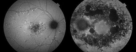
Geographic atrophy that appears as a “window defect” in fluorescein angiography will appear dark in autofluorescent imaging. Focal areas of increased FAF are often present in a junctional zone adjacent to existing atrophy prior to progression of atrophy or development of new atrophic areas. Longitudinal FAF imaging allows precise tracking of progression of geographic atrophy.

In addition to age-related accumulation of lipofuscin, increased deposition also occurs in Stargardt disease, cone dystrophies, retinitis pigmentosa, and Best’s disease, suggesting there may be a common pathogenetic pathway of retinal degeneration in these conditions.14

As ongoing research further defines the role of lipofuscin in various retinal disease processes, we are likely to see increased interest and use of this imaging modality. FAF imaging may prove to be useful in monitoring novel interventional strategies targeted at slowing accumulation of toxic lipofuscin compounds.
In addition to the documentation of lipofuscin in the RPE, there are other fluorescent findings that may occur in the eye. Cataracts, pingueculae, calcific lesions and other fluorophores will all fluoresce when excited with light of specific wavelengths.
References:
- Kelly JS. Autofluorescence of drusen of the optic nerve head. ArchOphthalmol 1974;92: 263-264.
- Barry C, Singh J, Constable IJ. Are optic disc drusen exhibiting autofluorescence, pseudofluorescence or reflectance? J Ophthalmic Photography 2000;22:32-37
- Delori FC, CK Dorey CK, G Staurenghi G, et al. In vivo fluorescence of the ocular fundus exhibits retinal pigment epithelium lipofuscin characteristics. Invest Ophthalmol Vis Sci 1995;36:718-729.
- von Ruckman A, Fitzke FW, Bird AC. Distribution of fundus autofluorescence with a scanning laser ophthalmoscope. Br J Ophthalmol 1995;79:407-412.
- Clark TM. Scanning laser ophthalmoscopes. In: Saine PJ, Tyler ME, eds. Ophthalmic Photography: Retinal Photography, Angiography and Electronic Imaging. 2nd ed. Boston, Butterworth-Heinemann, 2002:306-321.
- Spaide RF. Fundus autofluorescence and age-related macular degeneration. Ophthalmology 2003;110:392-9.
- Spaide RF. Autofluorescence imaging with the fundus camera. In: Holz FG, Schmitz-Valckenberg S, Bird AC, Richard F. Spaide RF. Atlas of Fundus Autofluorescence Imaging. Berlin, Springer, 2007:49-54
- Bennett TJ, Strong JD. The effects of gain and noise in fundus autofluorescence imaging. J Ophthalmic Photography 2007;29 Supplement:87-92.
- Robson AG, Egan C, Holder GE, et al. Comparing rod and cone function with fundus autofluorescence images in retinitis pigmentosa. Adv Exp Med Biol 2003;533:41-47.
- Spaide RF, Klancnik JM Jr. Fundus autofluorescence and central serous chorioretinopathy. Ophthalmology 2005;112:825-33.
- Von Ruckmann A, Fitzke FW, Bird, AC. In vivo fundus autofluorescence in macular dystrophies. Arch Ophthalmol 1997;115:609-615.
- Sawa M, Ober MD, Freund KB, et al. Fundus autofluorescence in patients with pseudoxanthoma elasticum. Ophthalmology 2006;113:814-820.
- Hopkins J, Walsh A, Chakravarthy U. Fundus autofluorescence in age-related macular degeneration: an epiphenomenon? Invest Ophthalmol Vis Sci 2006;47:2269-2271.
- Schmitz-Valckenberg S, Holz FG, Bird AC, Richard F. Spaide RF. Fundus autofluorescence imaging – review and perspectives. Retina 2008;28:385-409.