Category Archives: Technical Tactics

Corona Fog

In the past month or so we’ve increased our testing volume after limiting patient visits during a government mandated stay-at-home order during the COVID 19 pandemic. As we’ve ramped back up, we’ve changed our procedures to limit the risk of transmitting the virus. We’ve instituted stringent cleaning protocols, and installed breath shields on some instruments. All clinical personnel now wear PPE (masks, goggles, gloves) and all patients are required to wear masks while in the clinic. We’ve adapted to this “new normal” pretty quickly and our testing volume is almost back to pre-pandemic levels.

Another part of our new normal is a novel clinical finding that seems to be related to the COVID 19 pandemic. Prior to the pandemic, I hadn’t observed this finding. As our numbers increased, I started noticing artifacts that I couldn’t immediately identify in IR fundus images using the Spectralis OCT. I’m wondering how many others in the field have noticed the same thing.

Prominent dark shadow in the infrared fundus image on the left made it challenging to get a good quality OCT image.

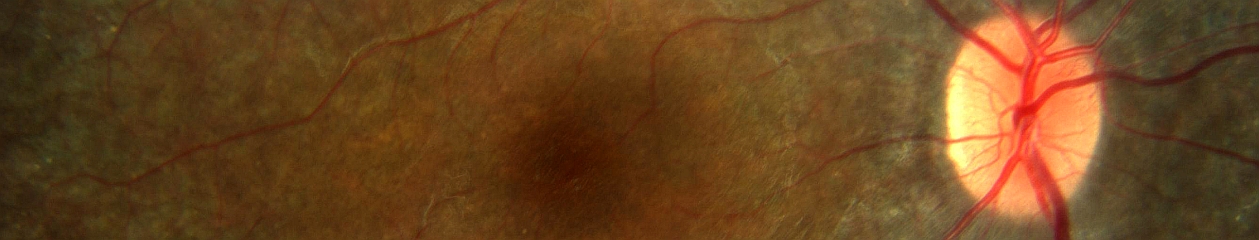
This patient came in two weeks ago. Here you see what appears to be vitreous hemorrhage or debris causing a dark shadow that obscures the view in the IR image. I really struggled to get good images. The OCT was adequate, but the accompanying IR fundus image was poor. Those of you that use the Spectralis know that any structure or pathology that is out of focus will typically appear dark because of the confocal pinhole that blocks scattered light from reaching the sensor. So it’s not uncommon to have a compromised view like that if there are media opacities such as dense cataracts, corneal opacities or vitreous pathology, so I didn’t think much of it at first.  

But then just two patients later I saw a similar artifact. This time it changed in appearance while I was imaging and got progressively worse. I had the patient sit back and re-positioned.

That seemed to improve the view, but within seconds it deteriorated again and got worse. It almost looked as if I were watching a vitreous hemorrhage occur live. I had the patient sit back yet again, waited several seconds, and resumed imaging. The artifact disappeared again!

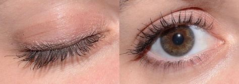
Finally, I looked around the device at the patient’s face to see if there was anything I was missing. And then I noticed it, the patient had an ill-fitting mask and was fogging the lens with her breath! The position of the mask forced her breath directly onto the lens surface of the Spectralis. Because of the confocal nature of the Spectralis, the pinhole aperture causes the artifact to appear dark rather than just a simple fogging seen with a slit lamp, fundus camera, or any other non-confocal device.

I asked a few of my astute imaging colleagues about this and a few had seen it but were initially stumped as well. Collectively we now believe we are seeing a new artifact related to patients wearing masks. One of my colleagues thought it was more prominent with the SPECTRALIS 102 degree wide angle lens. That may be because of the different working distance from the patient (closer).

Shadowing on a Spectralis fluorescein angiogram with 102 wide angle lens from breath fog.
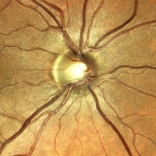
Image courtesy Gary Miller, CRA, OCT-C, FOPS

Looking back I realized that I had struggled with many patients during the peak of the lockdown. We were only seeing urgent/emergent patients at that time and were not routinely dilating patients in the interest of efficiency. So I assumed the darker fundus images were related to working with smaller pupils. It dramatically effects the confocal fundus image, but not always the OCT image because that component of the device is not confocal. The fogging seems to be more common with certain mask types or on days with high humidity.

Now when it occurs, I often just ask the patient to sit back for a few seconds until the fog clears clears and then resume imaging. Or we sometimes tape the top of the mask to the patient’s nose and cheeks to direct their breath down or to the side.

Changing the OCT working distance to the XL setting may reduce the fogging by changing the angle/distance from the patient’s mask.

Another trick is to change the OCT working distance (XL setting) as if you were trying to capture a longer eye. That effectively changes the angle between the patient’s mask and the front element.

My colleague Gary Miller and I have been unsuccessfully trying to come up with a catchy name for this finding. Here are a few of our attempts, but they’re all pretty lame.

Corona Fog
Pandemic haze
Mask mist
COVID condensation
Masquerade artifact

If you have a good one, put it in the comments section.

Here are the current recommendations from Heidelberg on cleaning optical surfaces in their devices. These recommendations seem pretty universal and would likely be similar to those from other manufacturers as well.

Update: A number of people have asked for a document to share whith coworkers. I created a quick pdf adaptation that can be found here.

Tim Bennett, CRA, OCT-C, FOPS

Monochromatic Anterior Segment Imaging

Monochromatic photography has a long history of use in ophthalmology. Illumination of the subject eye with light of a specific color can enhance the contrast and visibility of various structures or findings.  Traditionally, it is used in black-and white fundus photography to enhance anatomical details of the retina and choroid, but the same concept can also be applied to other parts of the eye.

Classic example of monochromatic green (red-free) rendition of fundus pathology. The green filter enhances the view to the retinal vessels and the macular lesion.

Monochromatic information can be captured by either filtering the light source (such as with a fundus camera), or placing a contrast filter in front of the camera lens to limit the color reaching the sensor. A subject color will appear lighter when photographed through a filter of the same color, and darker when photographed through a filter of its’ complementary or opposite color. For example, a red subject would appear lighter if exposed through a red filter and darker when photographed a complementary color filter, which in this case would be cyan (blue-green).

Red/Green/Blue color separations of a color fundus photograph of a choroidal nevus demonstrating the value on monochromatic rendering. The red channel shows a darkened lesion similar to the monochromatic effect using a red contrast filter. The blue and green channels suppress the view of the pigmented lesion.

In addition to the traditional technique of using monochromatic illumination with black-and-white photography, another alternative is to take full-color photos without filters and then use software to split the full color image into separate red, green, and blue color components.

Monochromatic views of a salmon colored conjunctival lesion. The lesion appears lighter than the conjunctiva in the red channel, while the blues channel darkens the lesion making it more apparent.

A similar effect occurs in this image of subconjunctival hemorrhage. It’s a great example of how subject colors that are the same as the channel or filter will appear lighter. The blood is darkened by the green and blue channel.

This is a remarkably simple way to obtain monochromatic renderings from any full color image. It works particularly well with color slit-lamp photos of the anterior segment.

A conjunctival lesion stained with lissamine green. Here the red channel darkens the stain pattern, while the green and blue channel lightens the blue-green dye.

One disadvantage to this method is the loss of resolution that occurs when viewing just a single channel that makes up the full color image. It also limits the available monochromatic information to just the three primary colors, red, green, and blue, but that’s usually sufficient for anterior segment applications.

Monochromatic renditions of corneal blood staining.

A dislocated cataract in the anterior chamber. Blue (which is the opposite color of yellow) darkens the lens almost completely, while the red channel enhances its appearance.

To Blink, or not to Blink?

It seems almost too obvious to mention, but just like you can’t see through a window when the window shade is pulled down, you cannot view or image the interior of the eye through closed eyelids.

close-open1-640

Obviously we need fully retracted upper and lower lids to get the best view of the fundus with our fundus camera, SLO, or OCT. Because these are noncontact imaging techniques, image quality is also dependent on a regular ocular surface and clear ocular media. An intact tear film is an important optical component of the ocular media. Simply put, to get the best images we need to strike a balance between fully retracted lids and frequent blinking to maintain the tear film.

miller pre-post-640
Top: Shadow from partially retracted upper lid appears at the bottom of the fundus image and degrades the OCT signal. Bottom: fully retracted lid improves the illumination of fundus image and improves signal strength in the OCT.

mccalister pre-post 640
Lashes partially obscure the retinal view in the top image. A fully retracted lid improves the view.

Many patients are nervous about their visual symptoms and what diagnosis the imaging procedure might detect. They often try hard not to blink during the session thinking it will help you get the best images. But their tear film will break up during this time and the view will become compromised until they blink again. And they often apologize for blinking!

To compound this dilemma, these imaging tests are often performed after a patient has undergone an extensive screening workup that includes IOP measurement, and application of topical anesthetic and dilating solutions. Patients may also undergo gonioscopy or macular contact lens examination prior to imaging. A disrupted tear film is an unintended side effect of these procedures and can adversely affect imaging quality.

pre-post blink 640
Top: irregular ocular surface causes degradation of both the fundus image and OCT as the tear film breaks up from lack of normal blinking. Bottom: after a few blinks, the view improves dramatically. Artificial tears would similarly improve the view.

It may seem counter-intuitive, but encouraging patients to blink frequently during imaging sessions can improve cooperation and image quality in fundus photography and OCT imaging. In our clinic, patients are often surprised that we encourage them to blink, having had procedures done in other clinics where they were sternly cautioned against blinking. In my experience as a consultant and workshop instructor, I have often heard OCT operators repeat the words “Don’t blink!” while performing a raster scan pattern that may take several seconds to capture.

cirrus blink2-640
Artifact from blinking during a volume scan. Timing the patient’s blinking pattern can avoid this type of artifact.

They know that a blink will result in an artifact in the volume map, but fail to recognize the need for frequent blinking. I don’t really blame the operator. Often that’s how they were taught to perform the scan during a workshop or training session by the manufacturer’s trainer:

“Don’t blink! Don’t blink! Don’t blink! Don’t blink! Don’t blink! Don’t blink! Don’t blink!….”

No wonder the patients are afraid to blink! Frequent blinking not only refreshes the tear film, it makes the patient feel more comfortable and ultimately more cooperative. You’ll soon learn to recognize a patient’s blinking rhythm and you can time your image capture just as their upper lid is retracting after a blink. Gently encourage the patient by saying, “hold your gaze for just a moment” when you need just a second or two longer to capture a good image. When frequent blinking doesn’t work, application of artificial tears can also make a difference in patients with dry eyes or compromised tear film.

blink clark 4-up-640
Partial versus fully retracted upper eyelid. Image quality is compromised by the lid and lashes in the left images. Gently retracting the upper lid immediately after the patient blinked improves image quality.

During fundus photography, the flash of the camera will cause an involuntary blink that helps refresh the tear film. If the lid or eyelashes obscure the view, gentle retraction of lids with a finger or q-tip may help. You don’t need to forcefully tug on the lid, just retract it a couple of millimeters to get any lashes out of the way and reveal the entire pupil. Patients are often still able to blink with this mild retraction of the upper lid.

So encourage your patients to blink regularly and learn to capture the best images in between the blinks. If it weren’t for all the blinks, anyone could do this job!

Adjusting the Eyepiece Reticle

One of the most fundamental yet difficult tasks for beginning photographers is proper adjustment of the focusing reticle of the traditional fundus camera. It is an essential element for capturing consistently sharp retinal photographs. The focusing reticle is the pattern of etched black lines, usually a cross-hair pattern, seen through the fundus camera eyepiece. The reticle is part of an aerial image focusing system like that used in microscopes.  An aerial image system is brighter than one that uses a ground glass screen like an SLR camera. In fundus photography the aerial image  is important. We need as bright a view as possible to keep the viewing illumination low enough for the patient to tolerate while still being able to see well enough to align and focus the instrument. Yet because the image is focused in “space” rather than on a ground glass, the reticle must match the same plane of focus as the fundus image.

fundus camera

The principle behind this adjustment seems simple enough, but there are some challenges associated with it. Setting the reticle adjusts for simple spherical refractive errors in the observer’s eye when their accommodation is relaxed at distance. You can think of this process as calibration of the optical system prior to focusing the fundus camera. The focus of your eye needs to be set at the same aerial focal plane as the camera. Simply put, both the crosshairs and the fundus need to be in focus at the same time. Set the reticle first and then adjust the focus of the camera.

reticle series2

In order to properly focus the fundus camera on a consistent basis, the photographer should relax their accommodation at distance to avoid accommoda­tive shift during photography. The reticle is then adjusted by turning the eyepiece until the cross hairs are sharp. The barrel of the eyepiece is marked in diopters of correction.  Since we are in the eyecare business, many of us know what our refractive error is, and you may be tempted to use that number as your reticle setting. Unfortunately, the diopter numbers may not be accurately marked on the eyepiece and can vary by manufacturer or instrument. So they can’t be relied on when switching from instrument to instrument. The reticle must be set correctly for each instrument.

eyepiece

You also can’t just set the calibration once and be done. A disadvantage to the aerial image is that your eye may change focus due to accommodation. Keeping the cross hair sharp requires constant awareness since your accommodation can change throughout the day due to fatigue or stress. Young photographers may struggle with keeping the eyepiece set properly because they typically have a greater ability to accommodate to near.  Early in my career, I often noticed that my eyepiece setting would change as the day went on. It would also change during the week, Mondays were different than Fridays and accommodation also changed with stress levels. Pay constant attention to the cross hairs and adjust the reticle if your accommodation drifts.

If you normally wear glasses or contact lenses, it is usually best to wear them while taking fundus photos rather than rely on the camera eyepiece to correct for your refractive error, especially if you have any astigmatism in your dominant (shooting) eye.

A popular and commonly taught technique for setting the eyepiece reticle involves adjust­ing the crosshairs at least three successive times, noting the diopter setting each time, and then using the average of these num­bers. This technique sounds like a good idea, but it can actually promote unnecessary accommodation and inaccurate settings. Each time the photographer looks at the num­bers marked on the eyepiece, they accommodate to near, then imme­diately try to relax at distance before looking through the viewfinder again. Repeating these steps multiple times induces accommodative “gymnastics” and subsequent fatigue that can lead to improper settings when accom­modation inevitably drifts during a photographic session.

OLYMPUS DIGITAL CAMERA

For this technique to work properly, someone other than the photographer should note and record the settings, so the photographer can keep accommodation relaxed at distance the entire time.

A better strategy is to ignore the eyepiece numbers altogether, but pay constant attention to the crosshairs and image of the retina. As long as the crosshairs and the aerial image of the fundus both appear sharp at capture, the focus will be correct in a system that is properly calibrated for parfocality.

For more on the basics of using the fundus camera visit the Fundus Photography page.


First Look: Eidon Retinal Scanner

I recently had the chance to get a hands-on look at the Eidon confocal retinal scanner.  The Eidon is a hybrid device combining features of a non-mydriatic fundus camera with confocal scanning technology. It is manufactured in Italy by Centervue SpA. Centervue describes this instrument as the first true color confocal scanner on the market. It is different than a confocal scanning laser ophthalmoscope in that it uses a broad spectrum white light LED (440-650 nm) rather than monochromatic lasers.  A second light source provides near infrared (IR) imaging at 825-870 nm. The advantage to confocal imaging is that it suppresses out-of-focus light from reaching the image sensor. This minimizes the effect of cataracts or other media opacities, resulting in sharp, high contrast images. The confocal design also allows it to image through a smaller pupil than a typical non-mydriatic camera.

eidon1The footprint of the Eidon is fairly compact, but the instrument is taller than most fundus cameras. The device is operated via touch screen tablet and has both automatic and manual controls.  The Eidon has a fixed 60 field of view, but is capable of capturing several fields and creating montage images. It features a 14 megapixel sensor to capture color, red free, and infrared images. The red free photos are extracted from the color image rather than through a separate exposure with a blue-green light source.

The capture software is incredibly simple to use. It is about as automatic as a device can get. Using the touch screen tablet, you enter the patient demographics and program it for the desired fields of one or both eyes and push the start button. The device does the rest automatically, even telling the patient to open their eyes prior to each flash capture.

Eidon2

The internal fixation light will step through the various fields and capture each one automatically. Auto-alignment is accomplished by identifying the center of the patient’s pupil with IR.  It will then focus automatically with a range of -12D to +15D. Once focused in IR, the camera will slightly readjust focus just prior to color capture to account for the difference in wavelengths between color and IR. The autofocus works very well, but eye movement during capture can contribute a slight blur to the image.

Minimum pupil size is 2.5mm. It does capture good images at this pupil size in the posterior pole view but like any other non-myd device, it works a little better if patients are pharmacologically dilated. This is especially helpful when imaging peripheral fields or you plan to do a montage. I have found this to be true with all non-myd color fundus cameras. I would like to see separate exposure settings to reduce the gain and noise for eyes with widely (pharmacologically) dilated pupils.

composite 4-640
Left to right: cropped images from a non-mydriatic camera, Optos composite red/green, and Eidon. Photos of the same pseudophakic eye were taken on different dates.

The resulting images appear different than what we see with either a digital fundus camera or a cSLO. Centervue refers to the broad spectrum imaging as “True Color” to distinguish Eidon images from SLO composite laser color images from Spectralis or Optos.

todd darker 640

The Eidon attempts to address some of the limitations of digital fundus cameras that are poorly calibrated for color balance, gamma, and exposure. In doing so, it seems to sacrifice some color fidelity and a true appearance of the optic nerve. The red channel is desaturated to avoid loss of detail from oversaturation, but many Eidon images appear slightly green and might benefit from a little more red or magenta bias to the color balance.

noise1

Although the pixel count of the Eidon sensor is quite high, the color images seem a little over-processed and a bit noisy when zoomed in, probably from  the increased contrast as well as the high gain settings that allow it to capture through very small pupils.

cropped nerveOne of the features touted by the manufacturer is that it prevents “optic disc bleaching” seen with some fundus cameras. It does hold detail in optic disc photos, but the flip side to this is that the rim of the nerve can appear abnormally dark or gray, making it difficult to document pallor. Disc bleaching shouldn’t be  a problem in fundus cameras that are calibrated for proper contrast and exposure.

disc compare2-640
Left: Traditional color fundus image with a well balanced 11 MP color sensor. Right: Same eye taken with Eidon.

I also played with the digital joystick and manual mode changing the level of focus to see if the instrument exhibited the confocal tonal shift seen with the Spectralis. In playing with manual mode to alter focus or exposure, it became clear that the instrument works best in full-auto mode.

ICSC3-640
We did not see the confocal tonal shift in either color or IR images when looking at elevated lesions or manually changing the focus. Left: Spectralis IR (820 nm) image of serous detachment exhibiting tonal shift from elevation. Right: Eidon IR (825-870 nm) does not demonstrate the same effect even though it is also a confocal device.

The Eidon review software is functional, but could be a little more streamlined. It would be nice to scroll though successive images, rather than having to go back and forth to the proof sheet to open each frame individually. The montage software works quite well.

montage darker 640

The bottom line is that the Eidon is a very interesting hybrid device that combines features of confocal scanning with full color capture in a package that is incredibly simple to use. It would be a great screening tool or replacement for a fundus camera in primary eye care settings and would require minimal staff expertise or training.

Thanks to Todd Hostetter, CRA, COMT for bringing the device to the clinic for a demo, and to Jim Strong, CRA, OCT-C for help taking some of the images.

Disclaimer: I have no financial or proprietary interest in this device.

The Confocal Tonal Shift

The Heidelberg Spectralis confocal scanning laser ophthalmoscope (cSLO) is a commonly used diagnostic imaging device that uses monochromatic laser illumination to image the eye. It can be used for several retinal imaging modalities including infrared reflectance (IR), fluorescein angiography, ICG angiography and fundus autofluorescence (FAF). The confocal capability of the cSLO allows it to capture high-contrast, finely detailed images.

But what does confocal actually mean and how does it work? The word confocal simply means “having the same focus”. In this case it refers to the confocal pinhole or aperture that is optically located at the same plane of focus as the subject. The cSLO utilizes a focused laser to scan the subject point-by-point and then captures the reflected light after it passes through a confocal pinhole. The pinhole suppresses out-of-focus light from reaching the image detector resulting in very sharp images. The confocal pinhole is especially effective at eliminating unwanted scatter from cataracts or corneal opacities since these structures fall far outside the plane of focus.

cataract
Left: Patient with a cataract obscuring the view of the retina and optic nerve through a fundus camera. Right: The confocal pinhole of the cSLO suppresses the scatter from the cataract improving the view of the fundus.

When imaging a patient, you can see the confocal effect as you adjust the focus to the plane of the retina where it is most light efficient. The image on screen will get brightest just as you come into sharpest focus. A secondary effect of the confocal aperture is how it effects the appearance of elevated or out of focus retinal structures.

papilledema1
The plane of focus effects reflectivity and appearance of retinal tissues based on depth due to the confocal aperture. All three images are at the same wavelength. Focus is on the elevated optic disc on the left image. Tonality changes as focus is shifted to the retinal surface.

Adjusting the focus knob of the Spectralis can have a dramatic effect on the tonal appearance of elevated structures such as papilledema or vitreous floaters as seen here in this video.

Note the optic nerve get progressively darker as focus is adjusted from the peak of the nerve to the surface of the surrounding retina, which starts to appear brighter. The opposite occurs in the second example. Vitreous floaters from asteroid hyalosis appear as dark shadows when focus is set on the optic nerve. As focus is shifted up into the vitreous, the floaters begin to brighten and the retina fades to  dark. The brightness/exposure has not been adjusted during this tonal shift.  The only change is the focus.

So what does this mean for us as diagnostic imagers? Because of the inherently shallow depth of focus of the cSLO, some ocular structures may appear dark simply because they are slightly out of focus. Elevated serous detachments or papilledema are examples of this phenomenon that I call the confocal tonal shift.

serous detachment 2
A case of central serous chorioretinopathy with a classic serous detachment that can be seen ophthalmoscopically. The cSLO image is dramatic in it’s appearance due to the confocal shift. The dark area is elevated and filled with clear fluid (not blood).

In some cases the confocal tonal shift can enhance the diagnostic information by clearly outlining the borders of an elevated area or lesion. The effect is most notable with the IR laser and in red free mode.

wavelength small
The confocal tonal shift in three different modalities. From left to right: IR, monochromatic blue, fundus autofluosescence. The effect seems to be most pronounced in IR mode.

The confocal tonal shift also has the potential to create tonal “artifacts” which can confound the appearance of findings like blood or hemorrhage that inherently appear dark.  Vitreous opacities will appear dark because they are usually out of focus and blocked by the confocal pinhole. But are they from blood or vitreous debris? It’s impossible to tell with the cSLO since they appear the same even though one is translucent and one is more opaque when viewed ophthalmoscopically or with a fundus camera.

vitreous floaters-640
Vitreous debris can appear very dark in cSLO images even though it is almost completely transparent. Without a frame of reference, it is impossible to know if these dark areas represent floaters or vitreous hemorrhage.

Similarly, it is difficult to distinguish between blood and elevation within retinal tissues in conditions such as macular degeneration, retinal vein occlusions and diabetic macular edema.

NPDR2-640
Patient with bilateral diabetic macular edema (DME). There are some associated dot and blot hemorrhages present, but the dark patches are a result of elevation from the DME. Each of these dark areas correspond to elevation on OCT.

brvo-640
Branch retinal vein occlusion (BRVO). The dramatic dark lesion is a result of both hemorrhage and elevation.

It is important to note that elevated lesions can appear dark regardless of the pathologic location in the fundus.  cSLO imaging alone can’t always differentiate the anatomic location. OCT imaging or angiography may be necessary to further investigate the location of the pathology.

comparison1-640
Left: choroidal tumor. Right: serous retinal detachment. Two very different disease processes but they appear quite similar because of the confoccal shift.

In some cases, the the confocal pinhole may suppress light that is reflected from the actual plane of focus, but is slightly blurred because of scattering from a lesion in tissue that is normally clear.

PAMM4-640
IR imaging with the cSLO can help identify paracentral acute middle maculopathy (PAMM). Although these lesions aren’t elevated, light scatter from the slight thickening in the middle retinal layers are suppressed by the confocal pinhole making the lesionappear dark. The findings are far more subtle in the color fundus photographs.

Although originally designed to image the retina, the cSLO can also be used to image the front of the eye. The confocal tonal shift may also effect the appearance of some anterior segment findings.

iris atrophy3
Patient with iris atrophy. The cSLO is focused on the surface of the iris which make these dark brown irides appear light at the plane of focus. The dark areas represent absence or thinning of the anterior iris surface. The deeper, out-of-focus, layers appear dark.

In addition to the confocal shift, light scattering from some corneal lesion types may also be suppressed by the pinhole contributing to the dark appearance of the lesion.

corneal opacity2 small
Corneal opacities shown with diffuse illumination and sclerotic scatter at the slit lamp. The cSLO image on the right more clearly delineates the extent of the lesion. Focus is at the level of the iris with the cornea being out of focus. Where the cornea is clear, there is no blocking effect from the confocal pinhole. But where there is scatter and reflectivity from the (out-of-focus) corneal lesion, this light is rejected by the confocal pinhole causing the dark appearance.

It is important to understand the confocal density shift when capturing or interpreting cSLO images and differentiate between structures that truly are dark from those that are simply out-of-focus. In some cases the tonal shift enhances areas of interest that may not be easily identified by other means. In others it may confound the documentation of blood  or hemorrhage. A second imaging modality such as color fundus photography, OCT or angiography is often needed to present a more complete diagnostic imaging study.

Here are a few more examples:

DME1-640
Diabetic macular edema (DME) appears dark on the IR image from the tonal shift and corresponds to the red (increased thickness) area on the OCT false-color thickness map.

examples
Left: cystoid macular edema (CME). Right: central serous chorioretinopathy.

examples1-640
Dark lesions on two separate patients diagnosed with one of the phakomatoses. Left: a patient with tuberous sclerosis and multiple hamartomas that appear dark from elevation. Right: a retinal hemangioma in von Hippel-Lindau disease. This blood filled lesion is dark from the blood itself rather than elevation

WagnerB not dark640
This case represents a rare exception to the tonal shift in an elevated lesion. Adjusting the focus up and down had little effect on the tonal density, except at the borders of the lesion. Note the very high reflectivity of the inner retina on OCT. Presumably the reflective surface of the elevated area was bright enough to attenuate the normal confocal shift.

Ocular Autofluorescence – More Than Just the Fundus

Over the past decade, fundus autofluorescence imaging has become a commonly used diagnostic technique to document the presence of fluorescent structures in the eye.1-2 The term “autofluorescence” is used to differentiate fluorescence that may occur naturally from fluorescence that is derived from application of dyes such as fluorescein or indocyanine green.

Autofluorescence is most commonly used to document fluorescence of lipofuscin, a fluorescent pigment that accumulates in the retinal pigment epithelium (RPE) as a normal byproduct of cell function.3 Lipofuscin deposition normally increases with age, but may also intensify in certain retinal abnormalities. It is used to document progression of macular degeneration, central serous chorioretinopathy, Stargardt disease, drug toxicities, and several hereditary retinal dystrophies.

In addition to the documentation of lipofuscin in the RPE, there are other fluorescent findings that may occur in the eye. One of the initial uses of autofluorescence was documenting optic disc drusen and astrocytic hamartomas as early as the 1970’s.4 Both of these entities are calcified lesions that are highly fluorescent and can be documented with standard fluorescein excitation and barrier filters.

Fig 1 small
Left: optic disc drusen. Right: astrocytic hamartoma, a calcific tomor associated with tuberous sclerosis

The aging crystalline lens is also known to be fluorescent. In fact, lens autofluorescence was the inspiration for the development of fluorescein angiography by Novotny and Alvis.

LENS faf2
Dense cataract that fluoresces with the standard fluorescein excitation and barrier filter combination in a fundus camera. This image illustrates how fluoresence from the lens can compromise the qulaity of a fluorescein angiogram by adding unwanted fluorescence.

In addition to these well-known entities, there are some additional autofluorescent findings you may encounter in the eye. In 2009, Utine et al reported autofluorescence of pingueculae on the ocular surface.5 This finding may interfere with photo-documentation of topical fluorescein staining patterns in patients with conjunctival lesions.

pinguecula2
Autofluorescence image of a pinguela taken with a fundus camera in external mode. Note that the crystalline lens of this eye also fluoresces.

Certain emboli, presumably calcific, exhibit fluorescence.

plaque3
Patient with a branch retinal artery occlusion. Left image demonstrates classic retinal whitening from the occlusion. Right image identifies the fluorescent calcific plaque associated with the arterial blockage.

We’ve also had a case of corneal blood staining that fluoresced. As it turns out, hemoglobin and hemosiderin are known to be fluorescent and that’s what fluoresced in this case.

hemosiderin
A case of corneal blood staining after a long standing hyphema. Autofluorescence is presumably from either hemoglobin or hemosiderin.

angioid
Another case where blood is hyperfluorescent in a patient with angioid streaks.

There may be other ocular findings that exhibit autofluorescence when excited with light of specific wavelengths. Have you noticed anything else that fluoresces? If so, I encourage you to share them.

  1. von Ruckman A, Fitzke FW, Bird AC. Distribution of fundus autofluorescence with a scanning laser ophthalmoscope. Br J Ophthalmol 1995;79:407-412.
  2. Spaide RF. Fundus autofluorescence and age-related macular degeneration.
    Ophthalmology 2003;110:392-9.
  3. Delori FC, CK Dorey CK, G Staurenghi G, et al. In vivo fluorescence of the ocular fundus exhibits retinal pigment epithelium lipofuscin characteristics. Invest Ophthalmol Vis Sci 1995;36:718-729.
  4. Kelly JS. Autofluorescence of drusen of the optic nerve head. ArchOphthalmol 1974;92: 263-264.
  5. Utine CA, Tatlipinar S, Altunsoy M, et al. Autofluorescence imaging of pingueculae. Br J Ophthalmol 2009;93:396–399.