All posts by Tim Bennett

Book Review

Optical Coherence Tomography and OCT Angiography: Clinical Reference And Case Studies

Darrin A. Landry, CRA, OCT-C
Amir H. Kashani, MD, PhD

Bryson Taylor Publishing, 2016
ISBN–‐13:978–‐1523976867
ISBN–‐10:1523976861
www.BrysonTaylorPublishing.com

In the early days of retinal angiography, photographers often worked very closely with ophthalmologists, learning together as they explored the diagnostic uses of fluorescein angiography and unraveled the complexities of interpreting the fascinating images they were capturing. This spirit of scholarly collaboration between imager and physician continues today in a new book: Optical Coherence Tomography and OCT Angiography, Clinical Reference And Case Studies by Darrin Landry and Amir Kashani. These authors are both well respected in their respective fields as educators and authors. Together they have created a timely textbook that will appeal to members of both professions.

Before receiving an advance copy of this book for review, I anticipated that the content would focus almost exclusively on OCT angiography.  I was pleasantly surprised to find that although the book features OCT-A prominently, it is much more than a text on this new state-of-the-art technology. It appropriately places OCT-A in the context of multiple imaging modalities to assist in diagnosis of a variety of retinal conditions.

The authors have produced a book that is part tutorial, part clinical atlas, and a collection of over forty cases that “puts it all together” using multiple imaging modalities with clinical descriptions. The book is divided into three sections:

Section 1. OCT and OCT Angiography

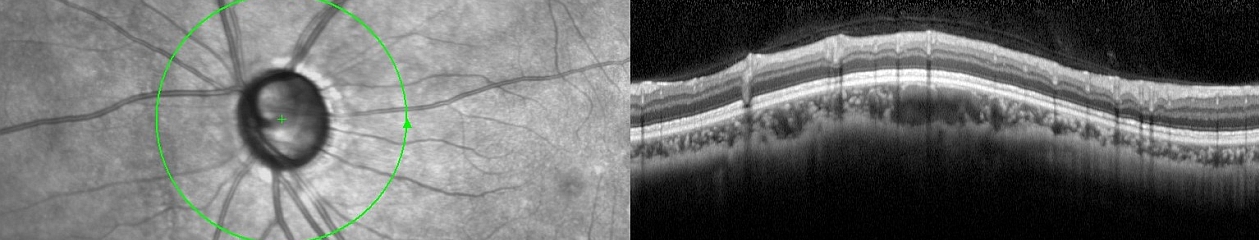
The introductory section will be particularly useful to imagers as it includes a basic overview of OCT and OCT-A technology, followed by a discussion on pattern recognition, normal anatomy and layers of the retina, how to move the scan pattern, recognizing artifacts, EDI/FDI and a basic primer on OCT-A. The OCT-A primer explains how this technology scans through the z-axis and detects motion to identify the retinal vasculature including the deep retinal plexus.  It includes a discussion of artifacts specific to OCT-A . This section will be especially helpful to those new to OCT and OCT-A, and anyone preparing for certification as an OCT-C.

Section 2. Atlas of Images and Disease Pathology

This section is an atlas of retinal OCT findings organized in anatomical order from the vitreous to the choroid. For each condition, the text includes a brief discussion of the disease process, clinical findings, and appearance in multiple modalities. For each condition, there are multiple image examples providing a full spectrum of potential findings for that disease. For instance, there are over twenty different examples of epiretinal membrane. Novice imagers will find this variety especially helpful in learning to recognize different manifestations of a single condition. In addition to common retinal findings the book also includes good examples of less recognized conditions such as outer retinal tubulation (ORT) and reticular pseudodrusen. As expected, retinal vascular diseases include OCT-A examples along with SD-OCT and other imaging modalities including fluorescein and ICG angiography. Experienced imagers will recognize many of these conditions, but the addition of OCT-A will give them another viewpoint and expand their understanding of each disease.

Section 3. Case Studies

The final section of the book is a series of over forty cases where the authors combine a brief medical summary with appropriate imaging modalities for clinical correlation. This format fits well with the current trend of “case-based-learning” in medical education. In many of these cases, OCT-A dovetails nicely with other imaging modalities to increase our understanding of a disease process or help confirm a diagnosis. This quote from the book’s Preface describes the format well “These images are presented in the context of additional imaging modalities to aide the reader in making useful correlations.”

In conclusion, this timely book is well organized and thorough, without becoming unwieldy. It is easy to navigate between sections if you want a quick reference on OCT anatomy or to look for examples of specific retinal conditions and how they may appear on OCT, OCTA and other imaging modalities. With over a thousand images and forty cases, to say that this book is generously illustrated would be an understatement. It is an impressive collaboration between an ophthalmic imager and a retinal specialist that should appeal to a wide audience that would include ophthalmic imagers, retinal technicians, residents in training, and clinicians wanting a reference for clinical correlation between modalities.

From a personal standpoint, I think it’s great to have an ophthalmic imager making a significant contribution to the ophthalmic literature. Darrin’s collaboration with Dr Kashani serves as a model for what imagers can accomplish when we collaborate with physicians on a professional level.  The spirit of collaboration between professions is echoed several times in the book including this statement from the Introduction, “Constant and close communication between the physician and imager is very essential.”

Reviews like this often end with a cliché that suggests that everyone in the profession should “add this book to your collection” or “keep a copy on your bookshelf”. I’ve tried to avoid those clichés, but honestly, I am happy to have this book in my collection and plan to keep it handy in clinic for reference, especially as we integrate OCT-A into our own diagnostic armamentarium.


World Photo Day

August 19th is recognized as World Photo Day, an international celebration of photography. This date marks the anniversary of the public unveiling of the Daguerrotype by the French government in 1839. It is an important milestone in the history and evolution of photography.

The story surrounding the invention of photography is both compelling and controversial. Several individuals claimed to be the true inventor of photography. The series of competing announcements by Louis Jacques Mandé Daguerre, William Henry Fox Talbot, and several others became a frantic race filled with secrecy, surprise, jealousy, financial reward, political maneuvering, and legal action.

To this day it’s still not entirely clear who was first to invent photography or exactly when, but history ultimately crowned a winner. Although Talbot (and others) made several significant early contributions Daguerre is generally given credit as the inventor of photography and August 19, 1839 is often recognized as the day that photography was born. Whether or not this is accurate is open to debate, but it seems a good a day as any to celebrate the history and evolution of the photographic arts.

You can join the celebration of World Photo day by taking and sharing some photographs on August 19th. If you want to know more about the controversial history surrounding the  invention of photography, visit: Milestones, Rivalries and Controversy: The Origins of Photography and Ophthalmic Photography

To Blink, or not to Blink?

It seems almost too obvious to mention, but just like you can’t see through a window when the window shade is pulled down, you cannot view or image the interior of the eye through closed eyelids.

close-open1-640

Obviously we need fully retracted upper and lower lids to get the best view of the fundus with our fundus camera, SLO, or OCT. Because these are noncontact imaging techniques, image quality is also dependent on a regular ocular surface and clear ocular media. An intact tear film is an important optical component of the ocular media. Simply put, to get the best images we need to strike a balance between fully retracted lids and frequent blinking to maintain the tear film.

miller pre-post-640
Top: Shadow from partially retracted upper lid appears at the bottom of the fundus image and degrades the OCT signal. Bottom: fully retracted lid improves the illumination of fundus image and improves signal strength in the OCT.
mccalister pre-post 640
Lashes partially obscure the retinal view in the top image. A fully retracted lid improves the view.

Many patients are nervous about their visual symptoms and what diagnosis the imaging procedure might detect. They often try hard not to blink during the session thinking it will help you get the best images. But their tear film will break up during this time and the view will become compromised until they blink again. And they often apologize for blinking!

To compound this dilemma, these imaging tests are often performed after a patient has undergone an extensive screening workup that includes IOP measurement, and application of topical anesthetic and dilating solutions. Patients may also undergo gonioscopy or macular contact lens examination prior to imaging. A disrupted tear film is an unintended side effect of these procedures and can adversely affect imaging quality.

pre-post blink 640
Top: irregular ocular surface causes degradation of both the fundus image and OCT as the tear film breaks up from lack of normal blinking. Bottom: after a few blinks, the view improves dramatically. Artificial tears would similarly improve the view.

It may seem counter-intuitive, but encouraging patients to blink frequently during imaging sessions can improve cooperation and image quality in fundus photography and OCT imaging. In our clinic, patients are often surprised that we encourage them to blink, having had procedures done in other clinics where they were sternly cautioned against blinking. In my experience as a consultant and workshop instructor, I have often heard OCT operators repeat the words “Don’t blink!” while performing a raster scan pattern that may take several seconds to capture.

cirrus blink2-640
Artifact from blinking during a volume scan. Timing the patient’s blinking pattern can avoid this type of artifact.

They know that a blink will result in an artifact in the volume map, but fail to recognize the need for frequent blinking. I don’t really blame the operator. Often that’s how they were taught to perform the scan during a workshop or training session by the manufacturer’s trainer:

“Don’t blink! Don’t blink! Don’t blink! Don’t blink! Don’t blink! Don’t blink! Don’t blink!….”

No wonder the patients are afraid to blink! Frequent blinking not only refreshes the tear film, it makes the patient feel more comfortable and ultimately more cooperative. You’ll soon learn to recognize a patient’s blinking rhythm and you can time your image capture just as their upper lid is retracting after a blink. Gently encourage the patient by saying, “hold your gaze for just a moment” when you need just a second or two longer to capture a good image. When frequent blinking doesn’t work, application of artificial tears can also make a difference in patients with dry eyes or compromised tear film.

blink clark 4-up-640
Partial versus fully retracted upper eyelid. Image quality is compromised by the lid and lashes in the left images. Gently retracting the upper lid immediately after the patient blinked improves image quality.

During fundus photography, the flash of the camera will cause an involuntary blink that helps refresh the tear film. If the lid or eyelashes obscure the view, gentle retraction of lids with a finger or q-tip may help. You don’t need to forcefully tug on the lid, just retract it a couple of millimeters to get any lashes out of the way and reveal the entire pupil. Patients are often still able to blink with this mild retraction of the upper lid.

So encourage your patients to blink regularly and learn to capture the best images in between the blinks. If it weren’t for all the blinks, anyone could do this job!

From Blogger to Scholar?

I always look forward to receiving my copy of the the Journal of Ophthalmic Photography in the mail. Even after reading digital proofs as an editor or contributing author it’s great to see the final product in print. There’s just something tangible and authentic about turning the pages of a high quality publication printed on good stock.

I was especially looking forward to the Spring 2016 issue of the JOP. It contains an article I contributed on The Confocal Tonal Shift. What’s unique about this article is that evolved from a blog post here on eye-pix into a scholarly article (of sorts).

The blog was based on an observational series of photographs that documents the tonal changes that occur when focusing the Heidelberg Spectralis, a confocal scanning laser ophthalmoscope (cSLO). I put the blog together to further my own understanding of just what I was seeing with the cSLO, and share my observations with fellow imagers. When asked to convert the blog into a piece for the JOP, I initially felt it was too informal, opinionated, and lacking strong references to be included in the professional literature.

web image2-640 crop

But the kernel of a good idea was definitely there. So I worked backwards and did a literature search after the fact. Then I reworked the article and was able to place my observations into the context of other clinical findings described in the ophthalmic literature. Probably not the ideal way to develop an idea into an article, but in this case it worked.

A mentor of mine has always encouraged me to get as much mileage as possible out of a project. The Confocal Tonal Shift is a good example of that. It’s gone from a blog post to a formal article in a well-respected professional journal. I’ve also adapted it into an expanded lecture topic (The Quirks of Confocal Imaging) that  I presented at a recent educational program. It received good feedback and will work it’s way into my lecture rotation this year.

The full journal article can be viewed here.

Bennett TJ. The confocal tonal shift.
Journal of Ophthalmic Photography, 38(1):17-22, Spring, 2016

“this camera takes great pictures”

When performing fundus photography or angiography, patients often ask about the technology used to help diagnose their ocular condition. After explaining that it’s a form of photography, the conversation will often turn to cameras. Patients sometimes ask for advice on what type of camera to buy for personal use. Often they’ll tell me about a particular camera they have and will invariably say “the camera takes great pictures”.

I’ve always found this expression and the concept behind it quite amusing. It assumes the person looking through the viewfinder and pressing the shutter button has nothing to do with it! On several occasions these conversations took place at a VA hospital while photographing vets. They’ll talk about having purchased a camera overseas, such as a Voigtlander, Zeiss Contax, or Leica in Europe during WWII, or a Nikon while stationed in Japan, Korea, or Vietnam. Without fail, they’ll tell me that “the camera takes great pictures”. All are quality cameras with good optics, but none of them are capable of taking pictures on their own. Someone has to compose the image and press the shutter.

A related misconception has occurred in ophthalmic imaging over the past decade. With all the automated features such as eye tracking, sampling, auto-alignment and  auto-exposure, etc. in the current crop of instruments, there is a perception that retinal imaging is simple and easy to perform. The implication is that the machine takes the picture, not the operator.

screengrab-640

It’s true that recent advancements in technology have improved and simplified image capture, but I still believe that skilled photographers produce the best diagnostic images. I once had a conversation with an overly-enthusiastic OCT salesman who claimed his instrument was better than the competition. As proof, he showed me two images of the same patient taken with two different OCT instruments. “See”, he said, “The competition’s instrument missed the pathology”. I corrected him saying that it wasn’t the instrument that missed the pathology, but the operator.

YurkovicD3 free scan
High resolution line scan of a small retinal arterial macroaneurysm captured using the free scanning technique.

This sparked an interesting debate. I argued that a skilled OCT operator, given appropriate direction from the ordering physician, would not have missed the area of interest. Ultimately we agreed it’s up to the operator to make the best use of the technology they have available.

Several famous photographers have weighed in on the relationship between camera and photographer in producing great images. I love these quotes:

“You don’t take a photograph, you make it.”
Ansel Adams

“The camera doesn’t make a bit of difference. All of them can record what you are seeing. But, you have to SEE”. 
Ernst Haas

“The camera is an instrument that teaches people how to see without a camera.”
Dorothea Lange

 “Photography is the art of observation… I have found it has little to do with the things you see and everything to do with the way you see them.”
Elliot Erwitt

“There is nothing worse than a brilliant image of a fuzzy concept.”
Ansel Adams

And finally, whenever someone states, “This camera takes great pictures”, I reply with another common quote that’s been attributed to several people, including boxing trainer Roger Mayweather, basketball great Charles Barkley, and possibly even Confucius:

“It ain’t the tools, it’s the carpenter”.

Lenz lens3-672
Slit-lamp photograph of dislocated intraocular lens implant and iris erosion shown in transillumination. Slit-lamp imaging relies on advanced photographic lighting techniques to accurately document the condition of the eye.

Voigtlander camera image from Wikimedia Commons: https://en.wikipedia.org/wiki/File:Vitorets.JPG#filelinks

Adjusting the Eyepiece Reticle

One of the most fundamental yet difficult tasks for beginning photographers is proper adjustment of the focusing reticle of the traditional fundus camera. It is an essential element for capturing consistently sharp retinal photographs. The focusing reticle is the pattern of etched black lines, usually a cross-hair pattern, seen through the fundus camera eyepiece. The reticle is part of an aerial image focusing system like that used in microscopes.  An aerial image system is brighter than one that uses a ground glass screen like an SLR camera. In fundus photography the aerial image  is important. We need as bright a view as possible to keep the viewing illumination low enough for the patient to tolerate while still being able to see well enough to align and focus the instrument. Yet because the image is focused in “space” rather than on a ground glass, the reticle must match the same plane of focus as the fundus image.

fundus camera

The principle behind this adjustment seems simple enough, but there are some challenges associated with it. Setting the reticle adjusts for simple spherical refractive errors in the observer’s eye when their accommodation is relaxed at distance. You can think of this process as calibration of the optical system prior to focusing the fundus camera. The focus of your eye needs to be set at the same aerial focal plane as the camera. Simply put, both the crosshairs and the fundus need to be in focus at the same time. Set the reticle first and then adjust the focus of the camera.

reticle series2

In order to properly focus the fundus camera on a consistent basis, the photographer should relax their accommodation at distance to avoid accommoda­tive shift during photography. The reticle is then adjusted by turning the eyepiece until the cross hairs are sharp. The barrel of the eyepiece is marked in diopters of correction.  Since we are in the eyecare business, many of us know what our refractive error is, and you may be tempted to use that number as your reticle setting. Unfortunately, the diopter numbers may not be accurately marked on the eyepiece and can vary by manufacturer or instrument. So they can’t be relied on when switching from instrument to instrument. The reticle must be set correctly for each instrument.

eyepiece

You also can’t just set the calibration once and be done. A disadvantage to the aerial image is that your eye may change focus due to accommodation. Keeping the cross hair sharp requires constant awareness since your accommodation can change throughout the day due to fatigue or stress. Young photographers may struggle with keeping the eyepiece set properly because they typically have a greater ability to accommodate to near.  Early in my career, I often noticed that my eyepiece setting would change as the day went on. It would also change during the week, Mondays were different than Fridays and accommodation also changed with stress levels. Pay constant attention to the cross hairs and adjust the reticle if your accommodation drifts.

If you normally wear glasses or contact lenses, it is usually best to wear them while taking fundus photos rather than rely on the camera eyepiece to correct for your refractive error, especially if you have any astigmatism in your dominant (shooting) eye.

A popular and commonly taught technique for setting the eyepiece reticle involves adjust­ing the crosshairs at least three successive times, noting the diopter setting each time, and then using the average of these num­bers. This technique sounds like a good idea, but it can actually promote unnecessary accommodation and inaccurate settings. Each time the photographer looks at the num­bers marked on the eyepiece, they accommodate to near, then imme­diately try to relax at distance before looking through the viewfinder again. Repeating these steps multiple times induces accommodative “gymnastics” and subsequent fatigue that can lead to improper settings when accom­modation inevitably drifts during a photographic session.

OLYMPUS DIGITAL CAMERA

For this technique to work properly, someone other than the photographer should note and record the settings, so the photographer can keep accommodation relaxed at distance the entire time.

A better strategy is to ignore the eyepiece numbers altogether, but pay constant attention to the crosshairs and image of the retina. As long as the crosshairs and the aerial image of the fundus both appear sharp at capture, the focus will be correct in a system that is properly calibrated for parfocality.

For more on the basics of using the fundus camera visit the Fundus Photography page.


First Look: Eidon Retinal Scanner

I recently had the chance to get a hands-on look at the Eidon confocal retinal scanner.  The Eidon is a hybrid device combining features of a non-mydriatic fundus camera with confocal scanning technology. It is manufactured in Italy by Centervue SpA. Centervue describes this instrument as the first true color confocal scanner on the market. It is different than a confocal scanning laser ophthalmoscope in that it uses a broad spectrum white light LED (440-650 nm) rather than monochromatic lasers.  A second light source provides near infrared (IR) imaging at 825-870 nm. The advantage to confocal imaging is that it suppresses out-of-focus light from reaching the image sensor. This minimizes the effect of cataracts or other media opacities, resulting in sharp, high contrast images. The confocal design also allows it to image through a smaller pupil than a typical non-mydriatic camera.

eidon1The footprint of the Eidon is fairly compact, but the instrument is taller than most fundus cameras. The device is operated via touch screen tablet and has both automatic and manual controls.  The Eidon has a fixed 60 field of view, but is capable of capturing several fields and creating montage images. It features a 14 megapixel sensor to capture color, red free, and infrared images. The red free photos are extracted from the color image rather than through a separate exposure with a blue-green light source.

The capture software is incredibly simple to use. It is about as automatic as a device can get. Using the touch screen tablet, you enter the patient demographics and program it for the desired fields of one or both eyes and push the start button. The device does the rest automatically, even telling the patient to open their eyes prior to each flash capture.

Eidon2

The internal fixation light will step through the various fields and capture each one automatically. Auto-alignment is accomplished by identifying the center of the patient’s pupil with IR.  It will then focus automatically with a range of -12D to +15D. Once focused in IR, the camera will slightly readjust focus just prior to color capture to account for the difference in wavelengths between color and IR. The autofocus works very well, but eye movement during capture can contribute a slight blur to the image.

Minimum pupil size is 2.5mm. It does capture good images at this pupil size in the posterior pole view but like any other non-myd device, it works a little better if patients are pharmacologically dilated. This is especially helpful when imaging peripheral fields or you plan to do a montage. I have found this to be true with all non-myd color fundus cameras. I would like to see separate exposure settings to reduce the gain and noise for eyes with widely (pharmacologically) dilated pupils.

composite 4-640
Left to right: cropped images from a non-mydriatic camera, Optos composite red/green, and Eidon. Photos of the same pseudophakic eye were taken on different dates.

The resulting images appear different than what we see with either a digital fundus camera or a cSLO. Centervue refers to the broad spectrum imaging as “True Color” to distinguish Eidon images from SLO composite laser color images from Spectralis or Optos.

todd darker 640

The Eidon attempts to address some of the limitations of digital fundus cameras that are poorly calibrated for color balance, gamma, and exposure. In doing so, it seems to sacrifice some color fidelity and a true appearance of the optic nerve. The red channel is desaturated to avoid loss of detail from oversaturation, but many Eidon images appear slightly green and might benefit from a little more red or magenta bias to the color balance.

noise1

Although the pixel count of the Eidon sensor is quite high, the color images seem a little over-processed and a bit noisy when zoomed in, probably from  the increased contrast as well as the high gain settings that allow it to capture through very small pupils.

cropped nerve
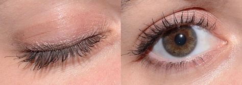
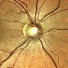
One of the features touted by the manufacturer is that it prevents “optic disc bleaching” seen with some fundus cameras. It does hold detail in optic disc photos, but the flip side to this is that the rim of the nerve can appear abnormally dark or gray, making it difficult to document pallor. Disc bleaching shouldn’t be  a problem in fundus cameras that are calibrated for proper contrast and exposure.

disc compare2-640
Left: Traditional color fundus image with a well balanced 11 MP color sensor. Right: Same eye taken with Eidon.

I also played with the digital joystick and manual mode changing the level of focus to see if the instrument exhibited the confocal tonal shift seen with the Spectralis. In playing with manual mode to alter focus or exposure, it became clear that the instrument works best in full-auto mode.

ICSC3-640
We did not see the confocal tonal shift in either color or IR images when looking at elevated lesions or manually changing the focus. Left: Spectralis IR (820 nm) image of serous detachment exhibiting tonal shift from elevation. Right: Eidon IR (825-870 nm) does not demonstrate the same effect even though it is also a confocal device.

The Eidon review software is functional, but could be a little more streamlined. It would be nice to scroll though successive images, rather than having to go back and forth to the proof sheet to open each frame individually. The montage software works quite well.

montage darker 640

The bottom line is that the Eidon is a very interesting hybrid device that combines features of confocal scanning with full color capture in a package that is incredibly simple to use. It would be a great screening tool or replacement for a fundus camera in primary eye care settings and would require minimal staff expertise or training.

Thanks to Todd Hostetter, CRA, COMT for bringing the device to the clinic for a demo, and to Jim Strong, CRA, OCT-C for help taking some of the images.

Disclaimer: I have no financial or proprietary interest in this device.

The Confocal Tonal Shift

The Heidelberg Spectralis confocal scanning laser ophthalmoscope (cSLO) is a commonly used diagnostic imaging device that uses monochromatic laser illumination to image the eye. It can be used for several retinal imaging modalities including infrared reflectance (IR), fluorescein angiography, ICG angiography and fundus autofluorescence (FAF). The confocal capability of the cSLO allows it to capture high-contrast, finely detailed images.

But what does confocal actually mean and how does it work? The word confocal simply means “having the same focus”. In this case it refers to the confocal pinhole or aperture that is optically located at the same plane of focus as the subject. The cSLO utilizes a focused laser to scan the subject point-by-point and then captures the reflected light after it passes through a confocal pinhole. The pinhole suppresses out-of-focus light from reaching the image detector resulting in very sharp images. The confocal pinhole is especially effective at eliminating unwanted scatter from cataracts or corneal opacities since these structures fall far outside the plane of focus.

cataract
Left: Patient with a cataract obscuring the view of the retina and optic nerve through a fundus camera. Right: The confocal pinhole of the cSLO suppresses the scatter from the cataract improving the view of the fundus.

When imaging a patient, you can see the confocal effect as you adjust the focus to the plane of the retina where it is most light efficient. The image on screen will get brightest just as you come into sharpest focus. A secondary effect of the confocal aperture is how it effects the appearance of elevated or out of focus retinal structures.

papilledema1
The plane of focus effects reflectivity and appearance of retinal tissues based on depth due to the confocal aperture. All three images are at the same wavelength. Focus is on the elevated optic disc on the left image. Tonality changes as focus is shifted to the retinal surface.

Adjusting the focus knob of the Spectralis can have a dramatic effect on the tonal appearance of elevated structures such as papilledema or vitreous floaters as seen here in this video.

Note the optic nerve get progressively darker as focus is adjusted from the peak of the nerve to the surface of the surrounding retina, which starts to appear brighter. The opposite occurs in the second example. Vitreous floaters from asteroid hyalosis appear as dark shadows when focus is set on the optic nerve. As focus is shifted up into the vitreous, the floaters begin to brighten and the retina fades to  dark. The brightness/exposure has not been adjusted during this tonal shift.  The only change is the focus.

So what does this mean for us as diagnostic imagers? Because of the inherently shallow depth of focus of the cSLO, some ocular structures may appear dark simply because they are slightly out of focus. Elevated serous detachments or papilledema are examples of this phenomenon that I call the confocal tonal shift.

serous detachment 2
A case of central serous chorioretinopathy with a classic serous detachment that can be seen ophthalmoscopically. The cSLO image is dramatic in it’s appearance due to the confocal shift. The dark area is elevated and filled with clear fluid (not blood).

In some cases the confocal tonal shift can enhance the diagnostic information by clearly outlining the borders of an elevated area or lesion. The effect is most notable with the IR laser and in red free mode.

wavelength small
The confocal tonal shift in three different modalities. From left to right: IR, monochromatic blue, fundus autofluosescence. The effect seems to be most pronounced in IR mode.

The confocal tonal shift also has the potential to create tonal “artifacts” which can confound the appearance of findings like blood or hemorrhage that inherently appear dark.  Vitreous opacities will appear dark because they are usually out of focus and blocked by the confocal pinhole. But are they from blood or vitreous debris? It’s impossible to tell with the cSLO since they appear the same even though one is translucent and one is more opaque when viewed ophthalmoscopically or with a fundus camera.

vitreous floaters-640
Vitreous debris can appear very dark in cSLO images even though it is almost completely transparent. Without a frame of reference, it is impossible to know if these dark areas represent floaters or vitreous hemorrhage.

Similarly, it is difficult to distinguish between blood and elevation within retinal tissues in conditions such as macular degeneration, retinal vein occlusions and diabetic macular edema.

NPDR2-640
Patient with bilateral diabetic macular edema (DME). There are some associated dot and blot hemorrhages present, but the dark patches are a result of elevation from the DME. Each of these dark areas correspond to elevation on OCT.
brvo-640
Branch retinal vein occlusion (BRVO). The dramatic dark lesion is a result of both hemorrhage and elevation.

It is important to note that elevated lesions can appear dark regardless of the pathologic location in the fundus.  cSLO imaging alone can’t always differentiate the anatomic location. OCT imaging or angiography may be necessary to further investigate the location of the pathology.

comparison1-640
Left: choroidal tumor. Right: serous retinal detachment. Two very different disease processes but they appear quite similar because of the confoccal shift.

In some cases, the the confocal pinhole may suppress light that is reflected from the actual plane of focus, but is slightly blurred because of scattering from a lesion in tissue that is normally clear.

PAMM4-640
IR imaging with the cSLO can help identify paracentral acute middle maculopathy (PAMM). Although these lesions aren’t elevated, light scatter from the slight thickening in the middle retinal layers are suppressed by the confocal pinhole making the lesionappear dark. The findings are far more subtle in the color fundus photographs.

Although originally designed to image the retina, the cSLO can also be used to image the front of the eye. The confocal tonal shift may also effect the appearance of some anterior segment findings.

iris atrophy3
Patient with iris atrophy. The cSLO is focused on the surface of the iris which make these dark brown irides appear light at the plane of focus. The dark areas represent absence or thinning of the anterior iris surface. The deeper, out-of-focus, layers appear dark.

In addition to the confocal shift, light scattering from some corneal lesion types may also be suppressed by the pinhole contributing to the dark appearance of the lesion.

corneal opacity2 small
Corneal opacities shown with diffuse illumination and sclerotic scatter at the slit lamp. The cSLO image on the right more clearly delineates the extent of the lesion. Focus is at the level of the iris with the cornea being out of focus. Where the cornea is clear, there is no blocking effect from the confocal pinhole. But where there is scatter and reflectivity from the (out-of-focus) corneal lesion, this light is rejected by the confocal pinhole causing the dark appearance.

It is important to understand the confocal density shift when capturing or interpreting cSLO images and differentiate between structures that truly are dark from those that are simply out-of-focus. In some cases the tonal shift enhances areas of interest that may not be easily identified by other means. In others it may confound the documentation of blood  or hemorrhage. A second imaging modality such as color fundus photography, OCT or angiography is often needed to present a more complete diagnostic imaging study.

Here are a few more examples:

DME1-640
Diabetic macular edema (DME) appears dark on the IR image from the tonal shift and corresponds to the red (increased thickness) area on the OCT false-color thickness map.
examples
Left: cystoid macular edema (CME). Right: central serous chorioretinopathy.
examples1-640
Dark lesions on two separate patients diagnosed with one of the phakomatoses. Left: a patient with tuberous sclerosis and multiple hamartomas that appear dark from elevation. Right: a retinal hemangioma in von Hippel-Lindau disease. This blood filled lesion is dark from the blood itself rather than elevation
WagnerB not dark640
This case represents a rare exception to the tonal shift in an elevated lesion. Adjusting the focus up and down had little effect on the tonal density, except at the borders of the lesion. Note the very high reflectivity of the inner retina on OCT. Presumably the reflective surface of the elevated area was bright enough to attenuate the normal confocal shift.

Ocular Autofluorescence – More Than Just the Fundus

Over the past decade, fundus autofluorescence imaging has become a commonly used diagnostic technique to document the presence of fluorescent structures in the eye.1-2 The term “autofluorescence” is used to differentiate fluorescence that may occur naturally from fluorescence that is derived from application of dyes such as fluorescein or indocyanine green.

Autofluorescence is most commonly used to document fluorescence of lipofuscin, a fluorescent pigment that accumulates in the retinal pigment epithelium (RPE) as a normal byproduct of cell function.3 Lipofuscin deposition normally increases with age, but may also intensify in certain retinal abnormalities. It is used to document progression of macular degeneration, central serous chorioretinopathy, Stargardt disease, drug toxicities, and several hereditary retinal dystrophies.

In addition to the documentation of lipofuscin in the RPE, there are other fluorescent findings that may occur in the eye. One of the initial uses of autofluorescence was documenting optic disc drusen and astrocytic hamartomas as early as the 1970’s.4 Both of these entities are calcified lesions that are highly fluorescent and can be documented with standard fluorescein excitation and barrier filters.

Fig 1 small
Left: optic disc drusen. Right: astrocytic hamartoma, a calcific tomor associated with tuberous sclerosis

The aging crystalline lens is also known to be fluorescent. In fact, lens autofluorescence was the inspiration for the development of fluorescein angiography by Novotny and Alvis.

LENS faf2
Dense cataract that fluoresces with the standard fluorescein excitation and barrier filter combination in a fundus camera. This image illustrates how fluoresence from the lens can compromise the qulaity of a fluorescein angiogram by adding unwanted fluorescence.

In addition to these well-known entities, there are some additional autofluorescent findings you may encounter in the eye. In 2009, Utine et al reported autofluorescence of pingueculae on the ocular surface.5 This finding may interfere with photo-documentation of topical fluorescein staining patterns in patients with conjunctival lesions.

pinguecula2
Autofluorescence image of a pinguela taken with a fundus camera in external mode. Note that the crystalline lens of this eye also fluoresces.

Certain emboli, presumably calcific, exhibit fluorescence.

plaque3
Patient with a branch retinal artery occlusion. Left image demonstrates classic retinal whitening from the occlusion. Right image identifies the fluorescent calcific plaque associated with the arterial blockage.

We’ve also had a case of corneal blood staining that fluoresced. As it turns out, hemoglobin and hemosiderin are known to be fluorescent and that’s what fluoresced in this case.

hemosiderin
A case of corneal blood staining after a long standing hyphema. Autofluorescence is presumably from either hemoglobin or hemosiderin.
angioid
Another case where blood is hyperfluorescent in a patient with angioid streaks.

There may be other ocular findings that exhibit autofluorescence when excited with light of specific wavelengths. Have you noticed anything else that fluoresces? If so, I encourage you to share them.

  1. von Ruckman A, Fitzke FW, Bird AC. Distribution of fundus autofluorescence with a scanning laser ophthalmoscope. Br J Ophthalmol 1995;79:407-412.
  2. Spaide RF. Fundus autofluorescence and age-related macular degeneration.
    Ophthalmology 2003;110:392-9.
  3. Delori FC, CK Dorey CK, G Staurenghi G, et al. In vivo fluorescence of the ocular fundus exhibits retinal pigment epithelium lipofuscin characteristics. Invest Ophthalmol Vis Sci 1995;36:718-729.
  4. Kelly JS. Autofluorescence of drusen of the optic nerve head. ArchOphthalmol 1974;92: 263-264.
  5. Utine CA, Tatlipinar S, Altunsoy M, et al. Autofluorescence imaging of pingueculae. Br J Ophthalmol 2009;93:396–399.

Camera Heritage Museum

camera museum small1On a recent trip through Virginia, I stumbled across a gem of a museum tucked away in historic downtown Staunton, VA. I had been browsing brochures of local attractions on a stand in the lobby of my hotel and spotted a photo of a vintage view camera. The brochure was for the Camera Heritage Museum. The non-profit museum bills itself as the largest camera museum on the East Coast. It wasn’t far from my hotel, so I decided to visit, not knowing what to expect.

I walked into what obviously had once been a camera store jam-packed with cameras of all shapes, sizes and vintages. There was a gentleman sitting behind a counter in the back, busy doing some maintenance on a camera. He looked up briefly, said hello, and went back to his work while I browsed through the impressive collection. I saw everything from miniature spy cameras to large format portrait view cameras.

I recognized some cameras that I had used in my early days in photography including a Crown Graphic 4×5 press camera, a Graphic View (first monorail view camera design), several early polaroid cameras, a 16 mm Minox and many others.

After a few minutes of browsing, I asked the man behind the counter a few questions about some cameras that I recognized. When I showed genuine interest in the cameras on display, he stepped out and started describing the history, significance and stories related to many of the items on display. His name was David Schwartz, and he is the curator of the museum. He’s a wealth of information. As more people entered the museum, he recounted some of the same stories several times over, each time with the enthusiasm of someone that clearly loved cameras and the history of photography.

The collection includes vintage view cameras, military cameras, spy cameras, aerial cameras, stereo cameras, underwater cameras, Kodak Brownies, Hasselblads, Leicas, Voigtlanders, Nikons, and some truly unique cameras including a 40″ long baseball camera with lever activated focus stops preset for the distance to each of the bases on the diamond.

Folmer Graflex Baseball Camera

David and I talked about some of the stereo cameras on display and I told him that as a medical photographer I regularly take stereo photos of human retinas. He nodded and directed me to a case which held a collection of Topcon 35mm cameras including a body from a vintage Topcon fundus camera.

OLYMPUS DIGITAL CAMERA
A Topcon 35mm camera back from a fundus camera is tucked in the back of this glass case.

When I explained a little bit more about fundus photography, he listened intently and I can imagine that he’ll include some of what I told him about this equipment in explanations to future museum visitors.

The venue for this museum is a little quirky, but it houses a serious collection of over 2000 cameras, photos and accessories. A unique feature is the fact that it is an open and accessible to the public, rather than a private collection. The museum also has an online presence. Their website contains a wealth of information on the history of photographic equipment, especially the online gallery of some of the many cameras in their collection. It’s a great resource for history buffs and vintage camera enthusiasts.

museum4

The museum can be found at the old Camera and Palette store at 1 West Beverley Street in Staunton, VA. If you are travelling through the area, it is definitely worth a visit. Better yet, if you have some old film cameras collecting dust in a closet you might want to consider contributing to the collection by donating them to the museum. They are always looking for cameras, photos and accessories with historic significance.